32 | Regency
®
CLASSIC C34-10 Direct Vent Freestanding Gas Stove
|
32
installation
REMOTE CONTROL
INSTALLATION
Use the Regency
®
Remote Control Kit supplied
with this unit. Use of other systems may void your
warranty.
The remote control kit comes with a hand held
transmitter, a receiver and a wall mounting plate.
CAUTION
Do not wire millivolt remote control
wires to the
120V AC wires
1. Install 3 AAA alkaline batteries in transmitter and
4 AA alkaline batteries in the receiver. Install
the receiver and its cover in the wall. Switch
the remote receiver to "remote" mode. The
remote control is now ready for operation.
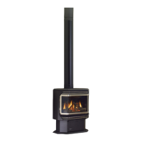
DOOR HANDLE
Attach spring handle by rotating counter clockwise
onto rod. Ensure that the spring ts into the entire
length of the rod.
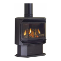
SAFETY SCREEN
INSTALLATION / REMOVAL
1. Install slotted brackets (found in the manual pack)
to the back of the door with 2 screws on each
side as shown below.
DO NOT TRY TO TURN
DOOR HANDLE!
IT IS NOT DESIGNED
TO BE MOVED.
OPTIONAL WALL
THERMOSTAT
A wall thermostat may be installed if desired.
Connect the wires as per the wiring diagrams.
Note that the wires are connected to the "TH" on
the gas valve. Use table below to determine the
maximum wire length:
Note: Preferable if the thermostat is installed
on an interior wall.
Regency
®
offers an optional programmable
thermostat but any 250-750 millivolt rated non-
anticipator type thermostat that is CSA, ULC or
UL approved may be used.
CAUTION
Do not connect the millivolt
wall thermostat wires
to the 120V wires.
Thermostat Wire Table
Recommended Maximum Lead Length
(Two-Wire) When Using Wall
Thermostat (CP-2 System)
Wire Size Max. Length
14 GA. 50 Ft.
16 GA. 32 Ft.
18 GA. 20 Ft.
20 GA. 12 Ft.
22 GA. 9 Ft.
FINAL CHECK
Before leaving this unit with the customer, the
installer must ensure that the appliance is ring
correctly. This includes:
1. Clocking the appliance to ensure the correct
ring rate (rate noted on label) at 15 minutes.
2. If required, adjusting the primary air to ensure
that the ame does not carbon. First allow the
unit to burn for 15 min. to stabilize.
3. Check for proper draft.
CAUTION
Any alteration to the product that causes
sooting or carboning that results in damage
to the exterior facia is not the responsibility of
the manufacturer.
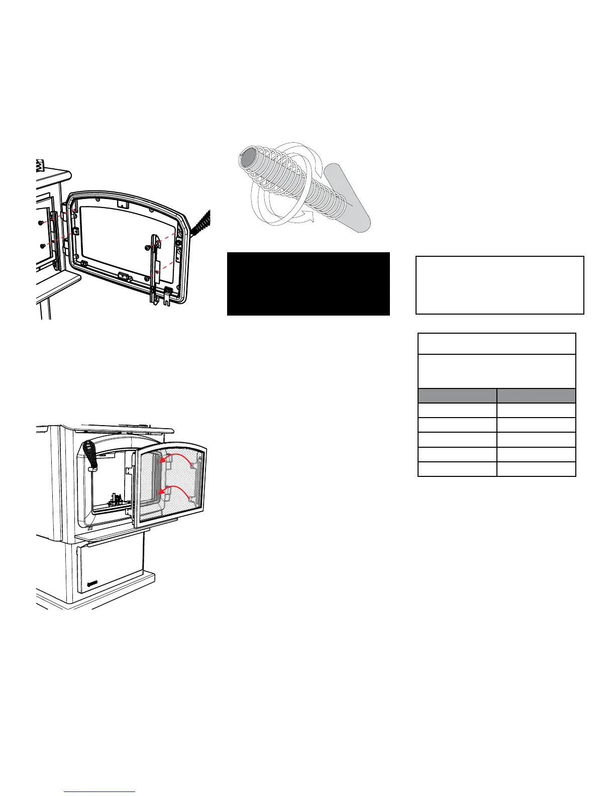
2. To install the safety screen, hook the tabs on the
safety screen into the slotted bracket on either
side of the glass door.
3. To remove the safety screen, lift up slightly and
pull forward.