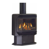
Regency
®
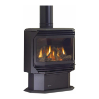
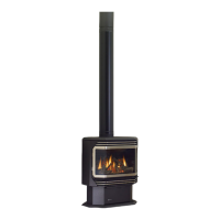
CLASSIC C34-10 Direct Vent Freestanding Gas Stove | 29
|
29
installation
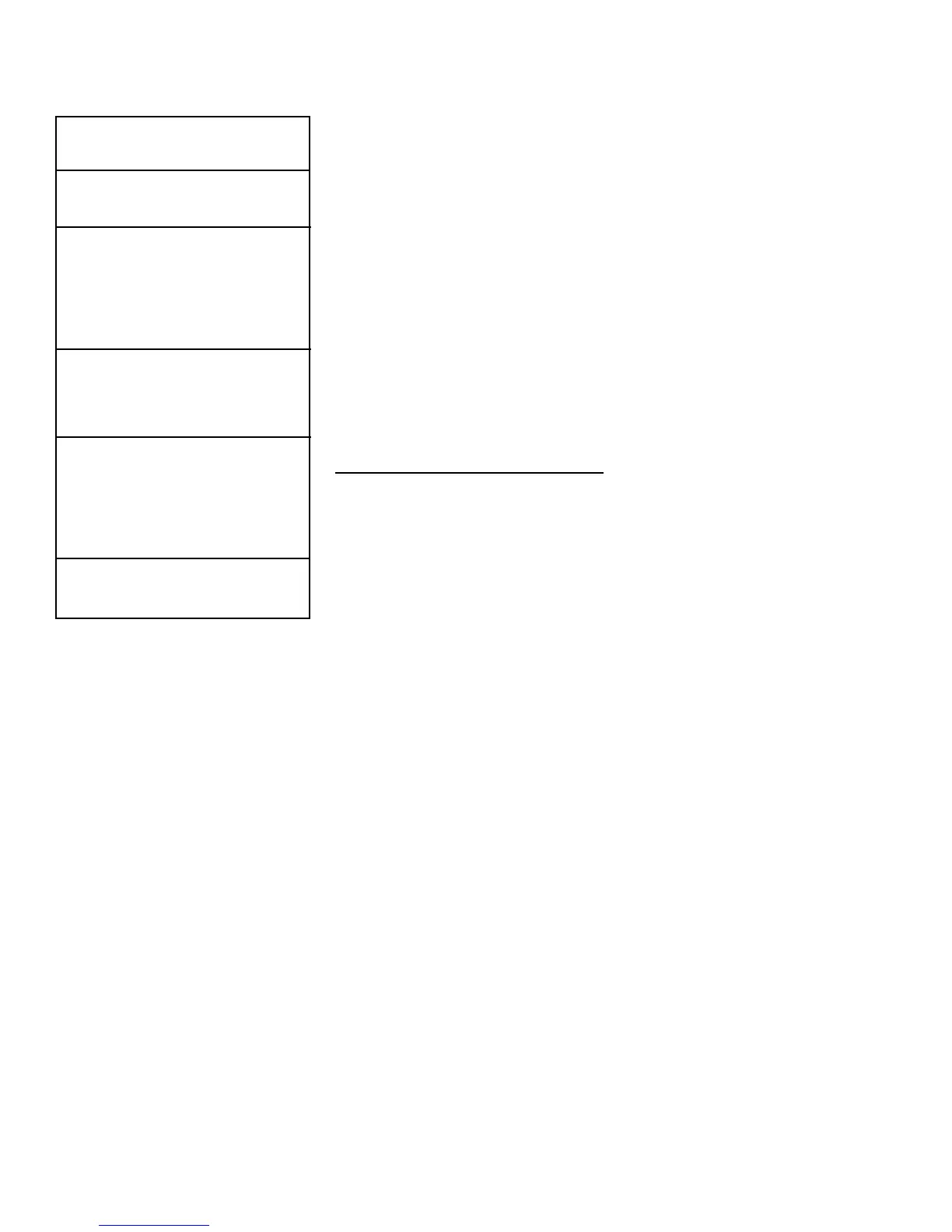
SYSTEM DATA
(For 0 to 4,500 feet altitude)
Orice Sizes:
Burner Natural Gas #36
Burner Propane #52
Max. Input Rating
Natural Gas 32,000 Btu/h
Propane 32,000 Btu/h
Min. Input Rating
Natural Gas 16,000 Btu/h
Propane 16,000 Btu/h
Supply Pressure
Natural Gas min. 5.0" w.c
max. 8.0" w.c.
Propane min. 12.0" w.c.
max. 13.0" w.c.
Manifold Pressure High
Natural Gas 3.8" +/- 0.2" w.c.
Propane 11" +/- 0.2" w.c.
Manifold Pressure Low
Natural Gas 1.1" +/- 0.2" w.c.
Propane 2.9" +/- 0.2" w.c.
Electrical: 115V_60 Hz less than 2 amp
Circulation Fan: 75/125 CFM.
Log Set: Ceramic ber, 4 per set.
Output capacity:
The efciency rating of the appliance is a
product thermal efciency rating determined
under continuous operating conditions and
was determined independently of any installed
system.
GAS CONNECTION
The gas connection is a 3/8" NPT rigid pipe. This
pipe is supplied separately and must be installed
at the left rear of the unit. See "Unit Dimensions"
section for diagram. The gas line can be rigid pipe
or to make installation easier, use a listed exible
connector and manual shut-off valve if allowed by
local codes, or copper if approved. For minimum
and maximum supply pressure see the System
Data table.
Note: During any pressure testing of the gas
supply piping system that exceeds test
pressures of 1/2 psig, this appliance
and its individual shut-off valve must be
disconnected from the piping system. If
test pressures equal to or less than 1/2
psig are used then this appliance must
be isolated from the piping system by
closing its individual manual shut-off
valve during the testing.
HIGH ELEVATION
This unit is approved in Canada for altitude 0 to
4500 ft. (CAN1 2.17-M90 with the orice supplied.
GAS PIPE PRESSURE
TESTING
The appliance must be isolated from the gas sup-
ply piping system by closing its individual manual
shut-off valve during any pressure testing of the gas
supply piping system at test pressures equal to or
less than 1/2 psig. (3.45 kPa). Disconnect piping
from valve at pressures over 1/2 psig (14" w.c.).
The manifold pressure is controlled by a regulator
built into the gas control, and should be checked
at the pressure test point.
Note: To properly check gas pressure, both
inlet and manifold pressures should be
checked using the valve pressure ports
on the valve.
1. Make sure the valve is in the "OFF" position.
2. Loosen the "IN" (# 7. and/or "OUT" (# 7. pres-
sure tap(s), turning counterclockwise with a
1/8" wide at screwdriver.
3. Attach manometer to "IN" and/or "OUT" pres-
sure tap(s) using a 5/16" ID hose.
4. Light the pilot and turn the valve to "ON" posi-
tion.
5. The pressure check should be carried out with
the unit burning and the setting should be within
the limits specied on the safety label.
7. When nished reading manometer, turn off the
gas valve, disconnect the hose and tighten the
screw (clockwise) with a 1/8" at screwdriver.
Screw should be snug, but do not over tighten.