52
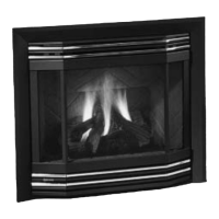
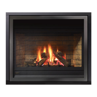
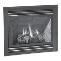
Regency® P33E-4 Zero Clearance Direct Vent Gas Fireplace
INSTALLATION
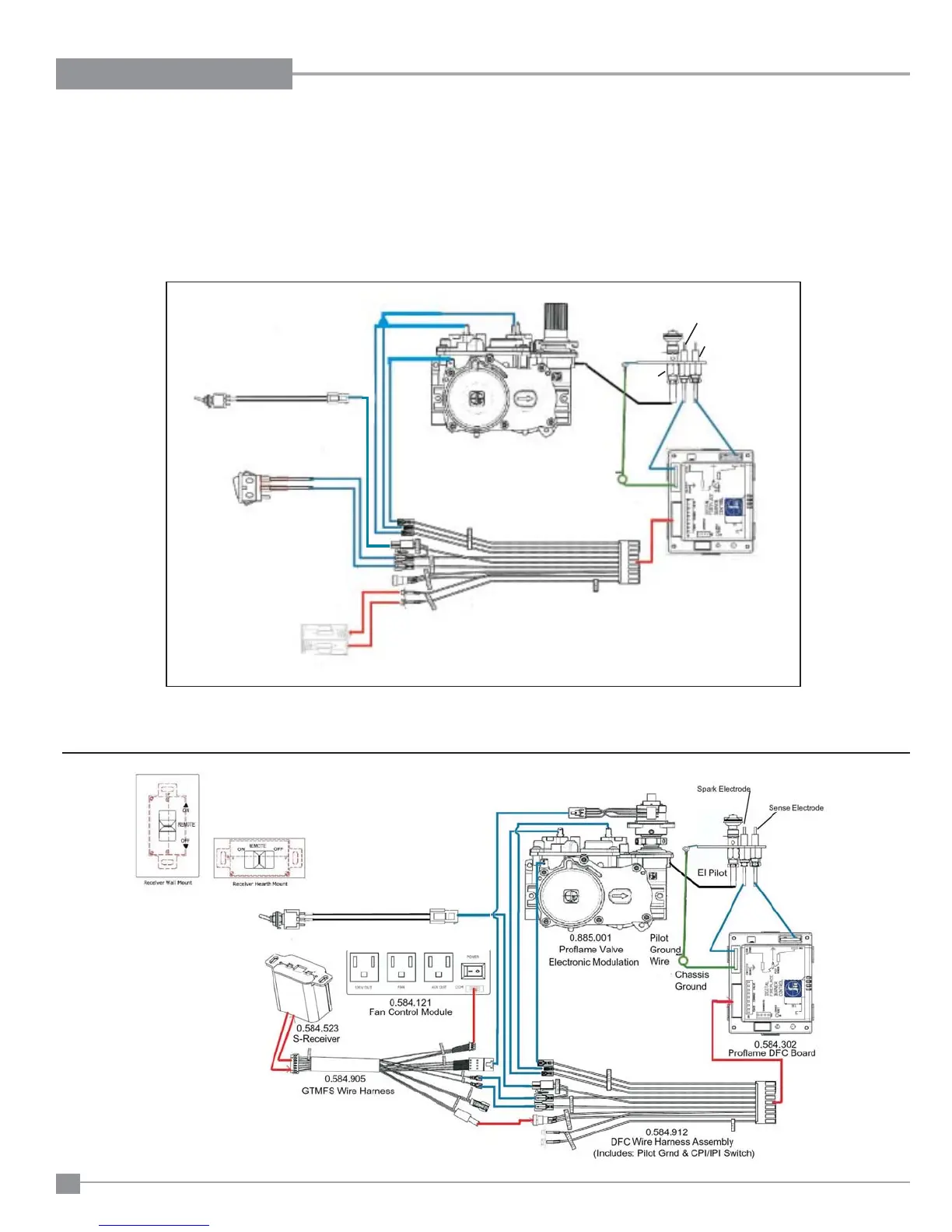
WIRING DIAGRAMS
This heater does not require a 120V A.C. supply for operation. In case of a power failure, the burner switch and the optional remote control/thermostat will
continue to operate. However, a 120V A.C. power supply is needed for the fan/blower operation.
(Do not cut the ground terminal off under any circumstances.)
NOTE: Even if the fan is not purchased with the unit, it is still a good idea to bring power to the receptacle box (provided with the unit) in case the
fan is installed at a later date.
Proflame System
Configuration
886 GTMF
Wire Diagram
SureFire™ Switch
Proame System
886 ON/OFF Stand Alone
Illustrated Wire Diagram
Surere Switch
(IPI / CPI)
Standard Main ON/OFF
Switch or Optional Wall Switch
Battery Holder
Pilot Ground Wire
Chassis Ground
EI Pilot
Sense Electrode
Spark Electrode
DFC Wire Harness Assembly
Proame DFC Board
886 Proame Valve
Note: 4 AA batteries must be installed to operate
the burner switch.
Do not use a 9 volt battery.
IMPORTANT:
If the optional remote control is used, the AA batteries normally installed into the battery holder must be removed. The AA batteries in the
receiver now operate the unit. Having AA batteries in both the battery holder and receiver will damage the gas valve.