V 11/2014
Temperature Control Unit 90smart/150smart Operating Instructions 13
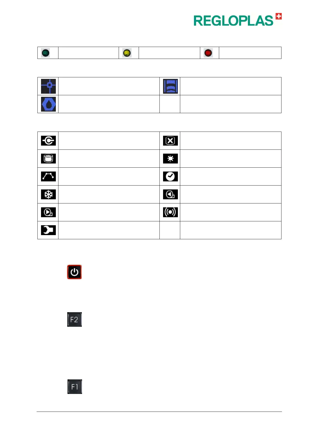
Status LEDs
Normal mode
Warning
Alarm
Device Functions
Set-point value toggling SP1/SP2 Draining (suction or blowing out)
Leak-stop mode
Symbols
Interface operation
Level of the heat transfer medium (filled
quantity) LOW
Level of the heat transfer medium (filled
quantity) OK
Heating
Ramp program activated
Timer activated
Cooling
Feed pump, counterclockwise rotation
Feed pump, clockwise rotation Alarm
Maintenance due (flashes if maintenance is
due)
RT70 Operation and Status Displays
In the off state of the RT70 control system, the message OFF appears in
the display area. Upon switching on with the ON/OFF button, the addi-
tional display is shown. The top left part of the display shows the set-
point temperature SP1 or SP2 (SP = Set point). The top right part of the
display shows the current outlet temperature (actual value of temperature
sensor Sn1, Sn2 or Sn3).
Sn1 = Outlet temperature
Three other selectable values are shown in the middle part of the display.
The additional display can be set by using the F2 key and by turn-
ing/pressing the RCD control knob (turning selects a value, pressing con-
firms it).
The symbols for set-point value display, suction operation (draining) and
leak-stop operation are shown in the lower left part of the display. The
various operational and status displays of the temperature control unit
are shown in the lower right part of the display.
Setting the Set-point values
The set-point values SP1 and SP2 are set by pressing the key F1. The
set-point value is then coloured light blue and can be set with the RCD