FIGURE 4
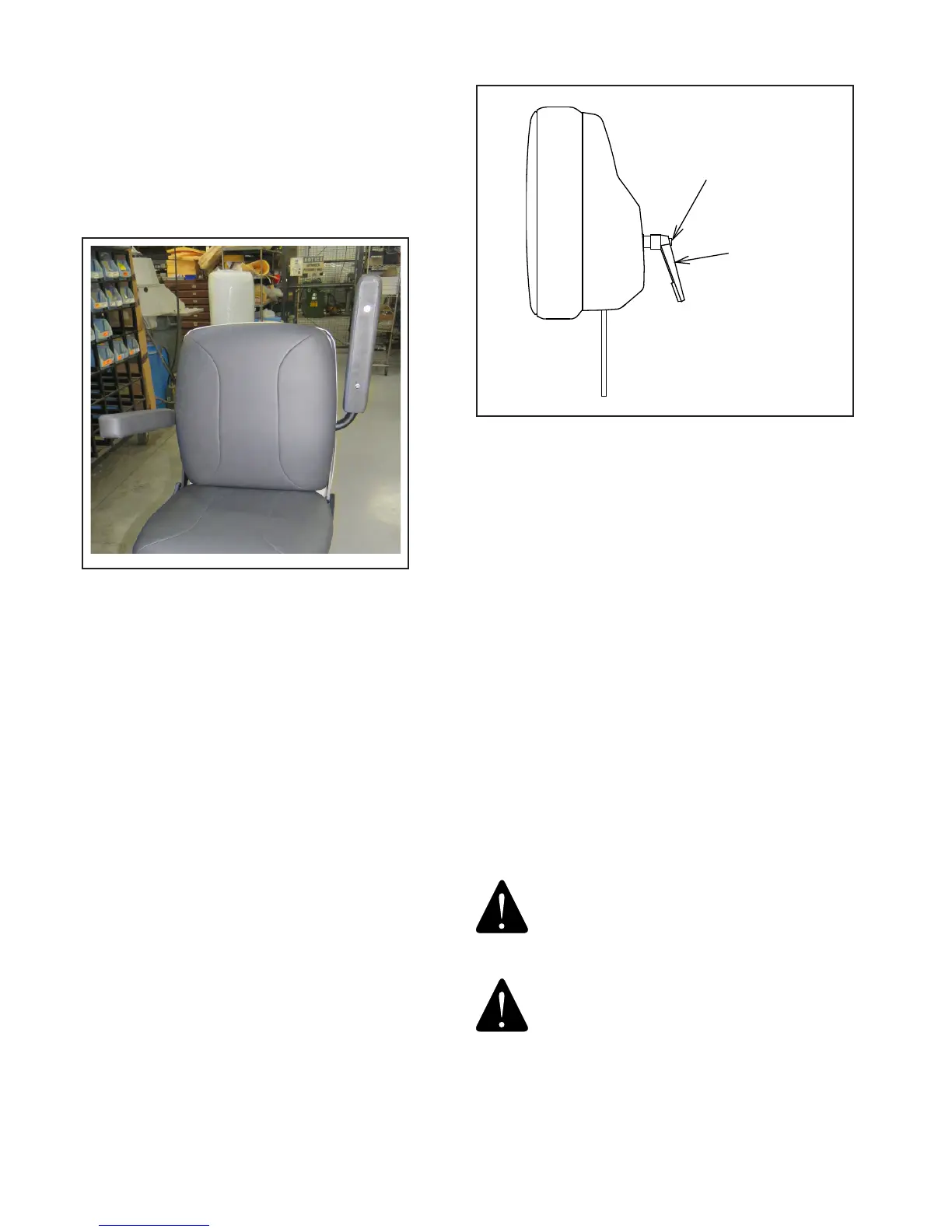
No. 11 Headrest
3.5.4. Operation-No. 10 Headrest
3.5.4.1. The No. 10 Headrest has a xed, rigid upholstered
backboard which supports a sliding, center pillow section.
For patient comfort simply move this pillow to a desired
position.
3.5.5. Operation-No. 18 Headrest
3.5.5.1. The No. 18 headrest is designed so it can be
operated with just one hand. To unlock, squeeze the clear
plastic actuator into Lock Housing. This will allow both pivots
of the articulating arm to rotate so the Headrest can be
moved to a new desired position. Once in the new position,
release the actuator. Make sure the actuator expands to its
original position fully exposing black dot on handle to insure a
positive lock. The headrest pad is free to rotate at all times.
(See Figure 5).
WARNING: IF THE NO. 18 HEADREST
RECEIVES AN IMPACT OR STRIKES AN
OBJECT WITH FORCE, CONTACT RELIANCE®
TECHNICAL SERVICE IMMEDIATELY..
AVERTISSEMENT : SI L’APPUIE-TÊTE # 18
REÇOIT UN CHOC OU FRAPPE UN OBJET
AVEC FORCE, CONTACTEZ IMMÉDIATEMENT
LE SERVICE TECHNIQUE RELIANCE®.
IN-30008
HANDLE
SCREW
3.4.2. To raise an arm simply lift upward. A stop limits upward
motion of the arm to a point parallel to the plane of the back
(Figure 3). At its lowest position, the arm will always be parallel
to the oor or horizontal (Figure 1). There is no lock in either
the upper or lower position. Both arms will articulate when
the Chair is reclined. In other words, the arms will remain in
a horizontal position regardless of how far back the Chair is
reclined.
3.5. Headrest
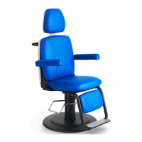
3.5.1. The No. 11 Headrest is the standard Headrest for
the Model 3000 Chair.
3.5.2. Operation-No. 11 Headrest
3.5.2.1. A single handle on the rear of the No. 11 Headrests
controls the locking mechanism. To unlock, grasp the handle
and turn counter clockwise. Change the tilt of the Headrest
until it is in the desired position. To lock, turn the handle
clockwise until snug. (Figure 4)
3.5.3. Adjustment-No. 11 Headrest
3.5.3.1. The handle on the outermost knob can be adjusted
to any preferred, locked position. Simply push in on the large
screw while pulling out on the handle. Rotate as desired,
and release. (Figure 4)
FIGURE 3