IN-3000
9
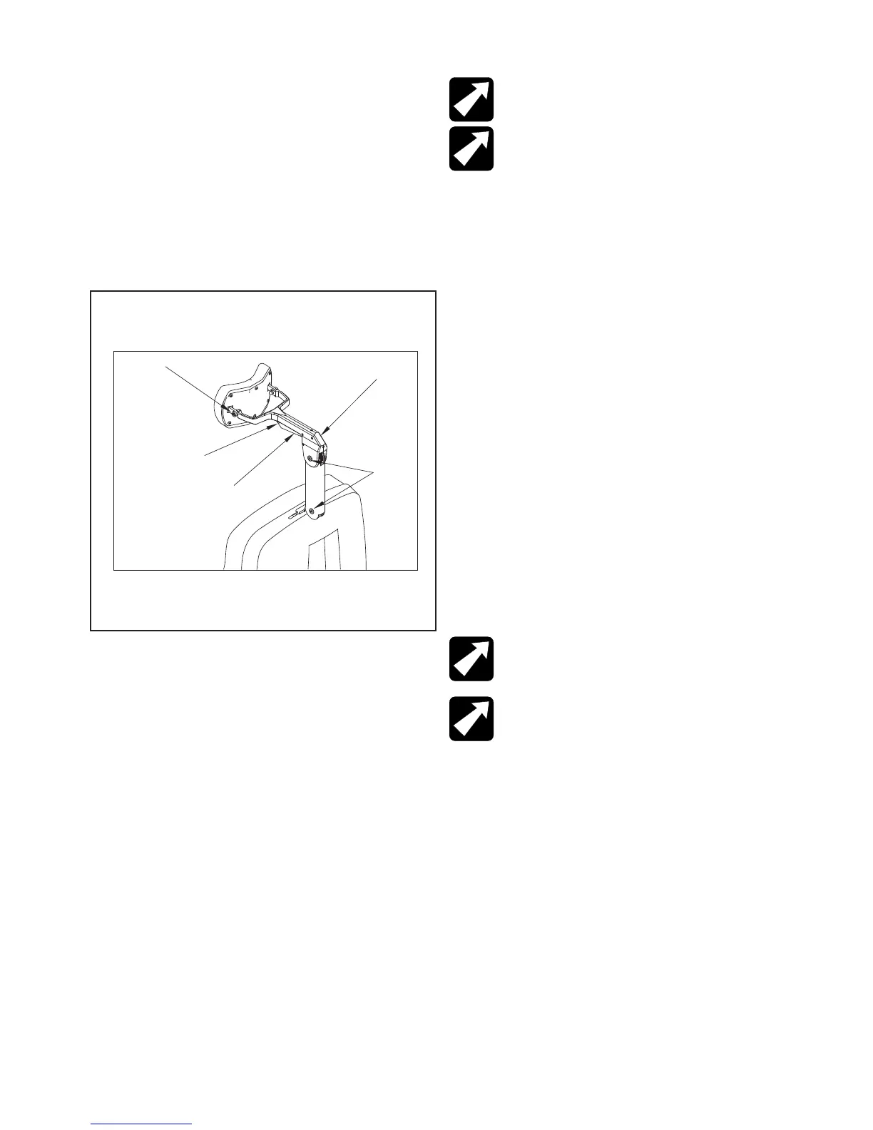
3.5.6. Adjustment-No. 18 Headrest
3.5.6.1. There are two adjustments provided on the No.
18 headrest. The rst is the tension on the pad rotation.
By tightening the two hex acorn nuts on the pad pivots with
a 3/8” open end wrench, the tension will be increased. To
adjust the drag on the pivots of the articulating arm, loosen
the set screw in the center of the pivot (Figure 5, item 1)
with a 3/32” hexagon key wrench. Next, tighten the pivot
screw on the other side of the pivot, with a 1/8” hexagon
key wrench. Now, retighten the set screw to retain the pivot
screw at the new adjustment. Either pivot may be adjusted.
FIGURE 5
No. 18 Headrest
3.6. Chair Back Cover Removal (for servicing
unit)
3.6.1. Remove the front of the seat-cushion assembly by
pulling straight out from the Chair. The seat cushions are
both attached with Velcro strips. This will permit access
to the seat-back.
3.6.2. Loosen the mounting screw (Figure 7, Item 6)
(slightly off-center in the Chair back). This screw is a
socket head set screw which requires a 1/8 hexagon key
allen wrench (included in the tool packet shipped with the
Chair) to loosen. Lift out the headrest.
3.6.3. Next, the Release Levers and Release Bar must
be removed from the Chair Back (Figure 7 Items 42, 43).
On both sides of the release lever, loosen the allen screw
about two turns using a 3/32” hexagon allen wrench.
1
2
Actuator
Black Dot
Acorn Nuts
NOTE: DO NOT TRY TO REMOVE SCREWS
COMPLETELY.
NOTE: N’ESSAYEZ PAS D’ENLEVER DES VIS
COMPLÈTEMENT.
3.6.4. Remove the release bar (Figure 7, Item 40) from
the release levers by pulling straight out.
3.6.5. On both sides of the release lever (Figure 7, Item
43) (closest to seat back), remove the allen screws
(Figure 7, Item 42) using a 1/8” hexagon allen wrench.
Pull the right side of the lever off, and then pull off the left
side (Figure 7).
3.6.6. From inside the seat back, remove the four lock
nuts (Figure 7, Item 28) using a 1/2” standard wrench.
3.7. Gas Spring Adjustment
3.7.1. Remove the Chair back cover per instruction 3.6.
3.7.2. Using a 9/16” or a 17 mm open-end wrench, turn
the jam nut clockwise to loosen on turn.
3.7.3. If Chair will not release:
a. Turn Gas Spring counter-clockwise (looking down on it)
until Seat Back can be reclined.
NOTE: BE SURE GAS SPRING ROD IS NOT
BACKING OUT OF MOUNTING CLEVIS (FIGURE
7, ITEM 25).
NOTE: SOYEZ SÛR QUE TIGE D’AMORTISSEUR
N’EST PAS SOUTENIR DE LA CHAPE DE
SUPPORT (LE SCHÉMA 7, POINT 25).
b. Turn Gas Spring clockwise just until SeatBack locks,
then another turn clockwise.
c. Test the mechanism by temporarily replacing one of
the Release Levers. Test the travel of the Chair back.
d. lf actuation is not correct, turn Gas Spring counter-
clockwise, working 1/8 turn at a time.
e. lf satised with actuation; tighten the jam nut up
against the Gas Spring pivot block. Remove the release
lever that was used for testing.