Activating the solar function
If the REMKO RBW domestic hot water heat pump is operated in conjunction with a thermal solar plant,
please note the following:
n T
o operate the heat pump in conjunction with max.7.5 m² solar collector surface, once the hydraulic con-
nection is established, it is also necessary to connect the collector probe supplied as standard. To do so,
use the appropriate measuring point on your collector surface and connect the probe to the connection
(Fig. 40), terminal 4. The solar collector pump is installed on terminal 2.
n Then remove the resistor, with which this connection is already equipped. This resistor should remain
with the unit, to ensure emergency operation in the event of a potential malfunction. If the REMKO RBW
domestic hot water heat pump is operated without the probe or resistor, an error is shown on the display.
Once installation of the thermal solar plant is complete and the collector probe has been connected, the
system is ready for operation. T
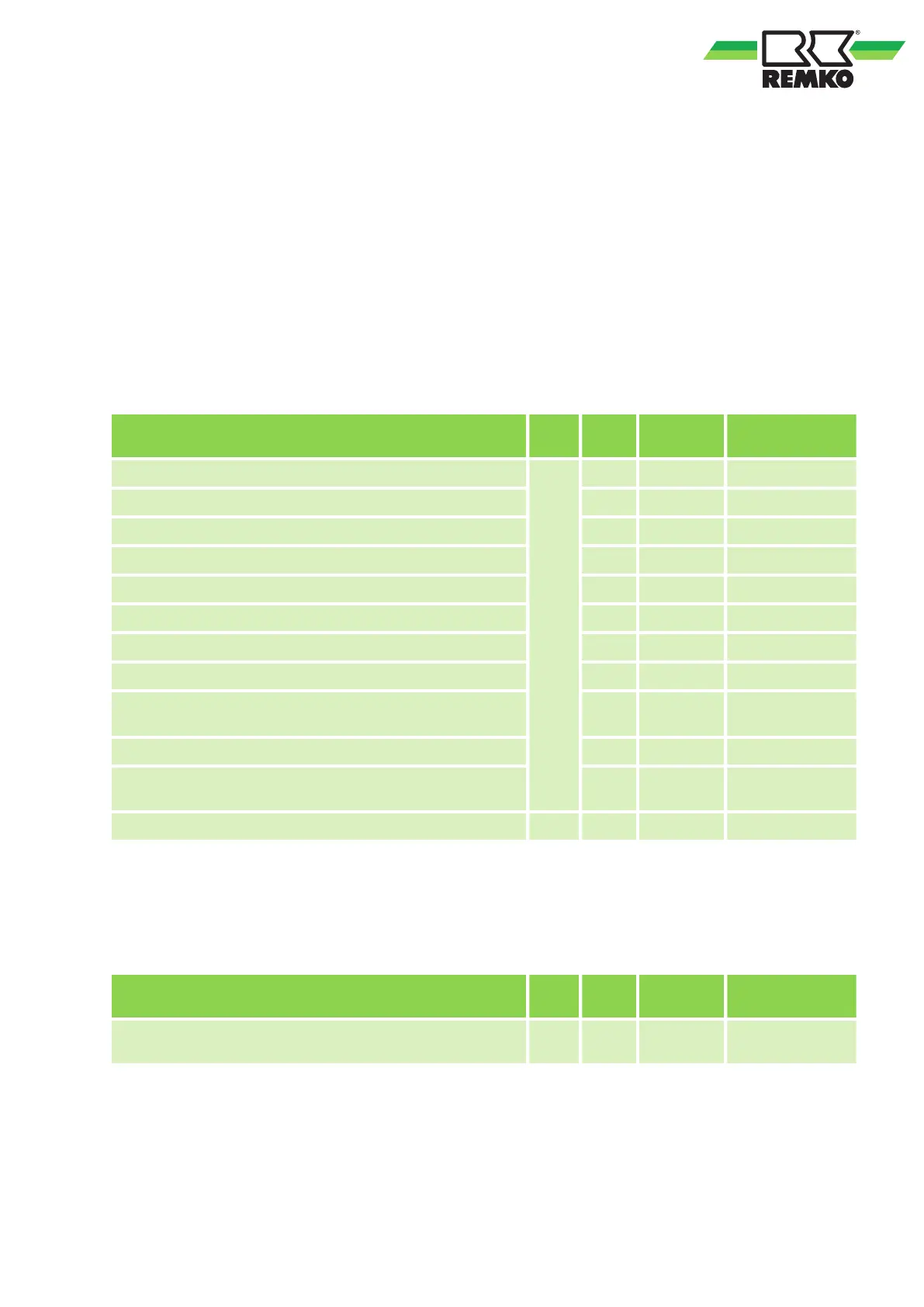
o optimise the installed system, it is also necessary to adjust the following
parameters on your system.
Description Code
Para-
meter
Value Range
Used storage tank probe solar
n
n01 0 0-bottom/1-top
Min. run-time solar pump n02 15 min 1-30 min
Start temperature difference solar n03 5°C 0~20 K
Night reduction n04 0/no 0-no/1-yes
Start time night reduction n05 00 h 00~23 h
End time night reduction n06 6 h 00~23 h
Start temperature night reduction n07 70°C 40~90°C
End temperature night reduction n08 10°C 1~40°C
Max. storage tank temperature for the solar changeover
valve
n09 70°C 50~90°C
Max. storage tank temperature solar pump stop n10 70°C 50~90°C
Solar pump operation storage tank temperature-inde-
pendent
n11 0/no 0-no/1-yes
Start collector temperature solar pump r r01 55°C 10~60°C
To adjust the parameters, perform the steps already described for configuring and activating the legionella
function in the relevant parameter menus.
Solar changeover valve
In order to increase solar yield, you have the option to use a changeover valve to charge an additional
storage tank (see example
Fig. 12)
Description Code
Para-
meter
Value Range
Max. storage tank temperature for the solar changeover
valve
n n10 70°C 50~90°C
To adjust the parameters for activating the changeover valve, perform the steps already described for acti-
vating the solar function in the relevant parameter menus.
45
 Loading...