EasyManua.ls Logo

Renesas E2 Emulator User Manual

Renesas E2 Emulator
30 pages
To Next Page IconTo Next Page
To Previous Page IconTo Previous Page
Page #27 background imageLoading...
Page #27 background image
E2/E2 Lite Notes on Usage
R20UT4582EJ0100 Rev.1.00 Page 27 of 30
Jul.16.19
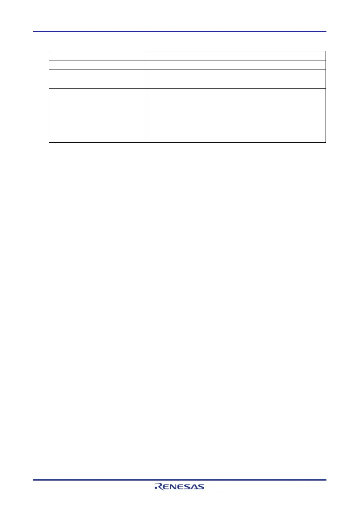
Table 3.1 Access to MPU-Protected Areas
Protected Area Operation of the Emulator Debugger
Arm MPU
Accessible
Bus master MPU The protected area is not accessible.
Slave MPU
Accessible
Security MPU On-chip SRAM/peripheral I/O registers
Reading: A dummy value (0x00) is read.
Writing: Writing is ignored.
Flash memory
Reading: A dummy value (0x00) is read.
Writing: Writing is possible if data are downloaded and written.
3.4 MCUs that are Used in Debugging
After debugging with the E2/E2 Lite, if the MCU is disconnected from the emulator and run on its own,
correct operation cannot be guaranteed. To operate the MCU on its own, use the programming software to
re-program the MCU.
MCUs that are connected to the E2/E2 Lite and used in debugging are placed under stress by repeated
programming of flash memory during emulation. Do not use MCUs that were used in debugging in mass-
production for end users.
3.5 Final Evaluation of the User Program
Before entering the mass-production phase, be sure to perform a final evaluation of the program which has
been written to the flash ROM by the programming software, without the E2/E2 Lite connected.

Table of Contents

Question and Answer IconNeed help?

Do you have a question about the Renesas E2 Emulator and is the answer not in the manual?

Renesas E2 Emulator Specifications

General IconGeneral
BrandRenesas
ModelE2 Emulator
CategoryComputer Hardware
LanguageEnglish

Summary

General Precautions for Microprocessing and Microcontroller Units

Overview of E2 and E2 Lite Emulators

E2 and E2 Lite Emulator Capabilities

Describes E2 and E2 Lite as on-chip debugging emulators for Renesas MCUs.

Designing the User System

Connecting Emulator to User System

Requirements for connecting the E2/E2 Lite to the user system via an interface cable.

Connector Installation on User System

Lists recommended connectors and interface cables for E2/E2 Lite system connection.

Connecting 20-Pin User System Interface Cable

Illustrates how to connect the user system interface cable to the E2/E2 Lite's 20-pin connector.

Connector Pin Assignments for User System

Shows specifications and pin assignments for 20-pin and 10-pin connectors used for SWD.

SWD Interface Pin Assignments (20-Pin & 10-Pin)

Details pin assignments for 20-pin and 10-pin connectors for SWD interface connection.

Recommended Circuit for Connector-MCU Connection

Presents recommended circuits for connecting the E2/E2 Lite connector to the MCU.

SWD Interface Circuit Connection

Shows a recommended circuit for SWD interface connection between connectors and MCU.

Connection Notes and Precautions

Provides important notes and wiring pattern recommendations for connecting the emulator.

RES# Pin Connection Details

Explains connection requirements for the RES# pin, with or without a reset circuit.

VCC Connection and Power Supply

Connects VCC and details E2/E2 Lite power supply capabilities and usage notes.

Notes on Emulator Usage

Power On/Off Procedures

Step-by-step procedures for safely turning the emulator and user system power on and off.

Emulator Debugger Usage Notes

Guidance on using the e² studio's debugger, including configuration and connection settings.

Connecting the Emulator Debugger

Notes on connecting the debugger, including reset state, startup mode, ID code, and ALeRASE command.

Flash Memory Reprogramming During Debugging

Details debugging operations involving flash memory reprogramming, allocation, conditions, secure area downloads, and flash breakpoints.

Related product manuals