E2/E2 Lite Designing the User System
R20UT4582EJ0100 Rev.1.00 Page 8 of 30
Jul.16.19
2. Designing the User System
2.1 Connecting the E2/E2 Lite with the User System
To connect the E2/E2 Lite, a connector for the user system interface cable must be mounted on the user
system.
When designing the user system, read this section of this manual and the hardware manual for the MCUs.
2.2 Installing the Connector on the User System
Table 2.1 and Table 2.2 list the recommended connectors and user system interface cables for the E2/E2
Lite, respectively.
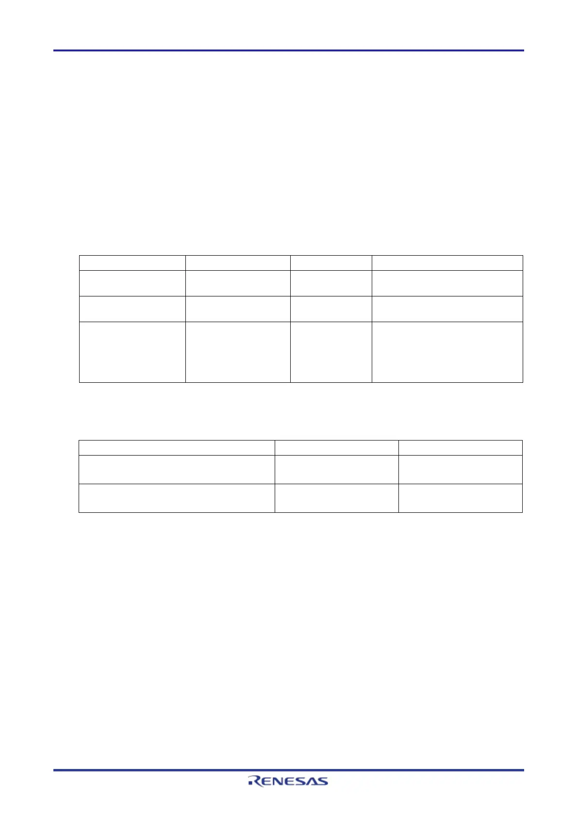
Table 2.1 Recommended Connectors
pitch) connector
20-pin surface-mount technology
(SMT) straight type
10-pin (1.27-mm pin
pitch) connector
FTSH-105-01-L-DV-K Samtec 10-pin SMT straight type
pitch) connector
(without a marking for
matching the position
of the connector;
keying shroud)
Note: When using a connector without a guide marking (keying-shroud type), take care with regard to the direction for
insertion of the cable.
Table 2.2 User System Interface Cables
20-pin to 20-pin cable*
(for the 20-pin (1.27-mm pin pitch) connector)
Comes with the product Separately sold
(for the 20-pin (1.27-mm pin pitch) connector)
Note: The 20-pin to 20-pin cable can be connected to the guideless 10-pin (1.27-mm pin pitch) connector; when doing
so, however, check the pin assignments and take care with regard to the direction for insertion of the cable.
Only connect the E2/E2 Lite after confirming that there are no mismatches of alignment on the user system
port connector. Incorrect connection will result in the host machine, the E2/E2 Lite, and the user system
emitting smoke or catching fire.