Renesas RA Family RA4 Quick Design Guide
R01AN5988EU0100 Rev.1.00 Page 44 of 51
Jul.21.21
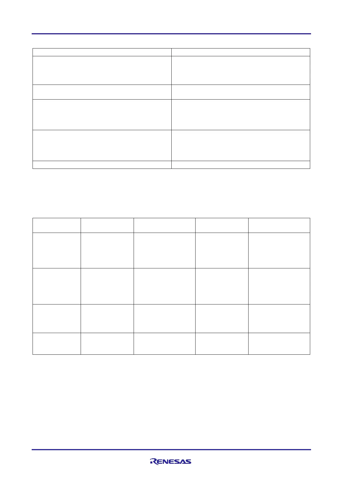
Table 16. Specifications of the lower power mode functions
Reducing power consumption by modifying clock
signals
The frequency division ratio can be selected
independently for the system clock (ICLK),
peripheral module clock (PCLKA, PCLKB, PCLKC,
PCLKD), and flash interface clock (FCLK).*
1
Functions can be stopped independently for each
peripheral module.
• Software Standby mode
• Snooze mode
•
Deep Software Standby mode
Three operating power control modes:
• High-speed mode
• Low-speed mode
•
Security attributes can be set for each register
Notes: 1. For details, see the chapter “Clock Generation Circuit” in the Hardware User’s Manual.
2. For devices that support TrustZone security features.
The following table lists the conditions to transition to low power modes, the states of the CPU and the
peripheral modules, and the method for cancelling each mode.
Table 17. Low Power Consumption Modes
1
All-Module Clock
Stop Mode
Deep Software
Standby Mode
condition
while
SBYCR.SSBY=0
SBYCR.SSBY=1 and
DPSBYCR.DPSBY=0
trigger in
Software Standby
mode.
SBYCR.SSBY=1 and
DPSBYCR.DPSBY=1
method
Any reset
available in the
mode.
this mode.
Any reset available in
the mode.
for this mode.
Any reset
available in the
this mode.
Any reset available in
the mode.
cancellation by
an interrupt
execution state
(interrupt
state (interrupt
processing)
execution state
(interrupt
cancellation by
Notes: 1. Refer to the table “Operating Conditions of Each Low Power Mode” in the Hardware User’s Manual
for additional details.
RA4 devices include register settings that allow the MCU to operate with lower power consumption in Normal
mode and Sleep mode. These modes are referred to as the Operating Power Control Modes and are
controlled by the OPCCR register.
The following is a summary of the Operating Power Consumption Control modes and the maximum
permissible clocking and voltage levels under each mode.

 Loading...


