Application Note U17209EJ1V0AN
12
CHAPTER 1 CONTROL METHOD
1.1 Outline of Brushless DC Motor Control
A brushless DC (BLDC) motor consists of a stator, coil, and rotor. The rotor, which includes a permanent magnet,
is rotated by the action of the magnetic field generated by the coil of the stator.
The magnetic field is generated by exciting the coil wound around the stator in a specific sequence. By controlling
the intensity and cycle of the magnetic field with a microcontroller, the torque response and the number of revolutions
of the motor can be controlled.
This section explains how to control a BLDC motor without a sensor by using the V850E/IA1, V850E/IA2,
V850E/IA3, V850E/IA4, or V850E/MA3.
Figure 1-3 shows an example of the circuit of a three-phase brushless DC motor. The internal PWM output
function of the microcontroller is used to control the current that flows through the motor, by using a transistor array
consisting of six transistors.
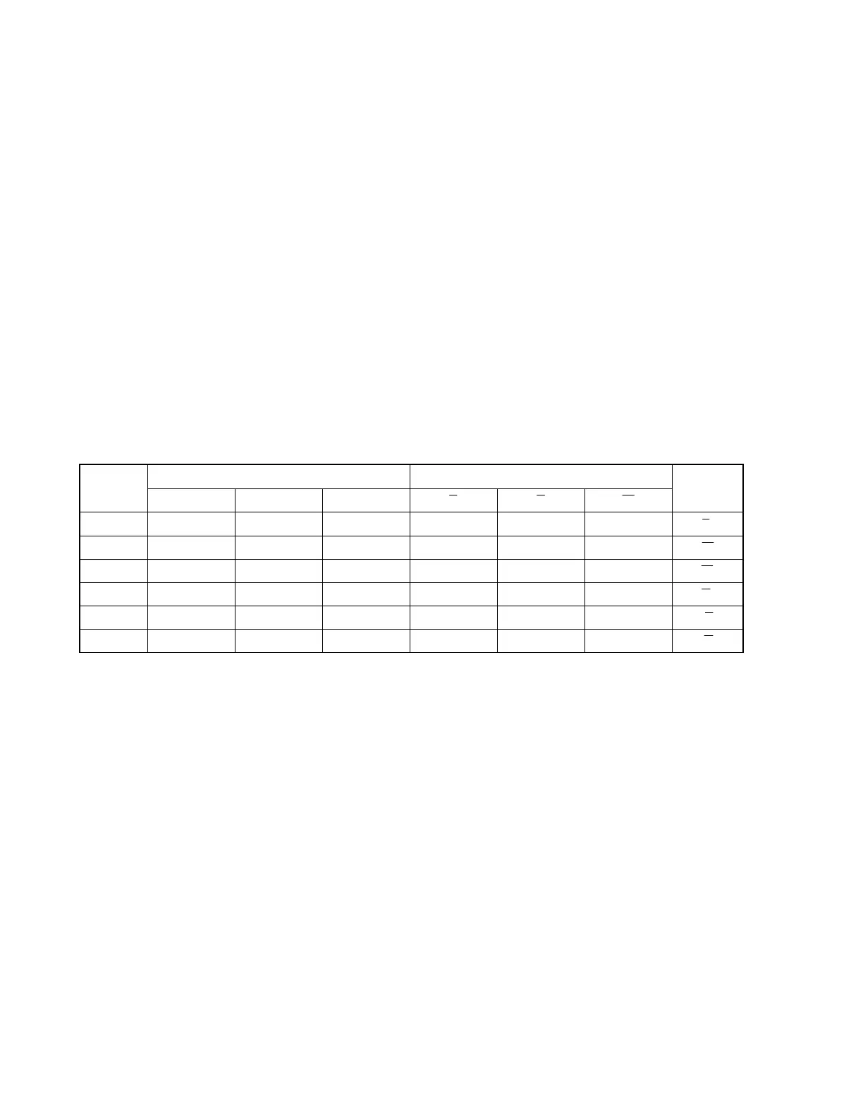
The magnetic field is generated by controlling the excitation pattern of the six transistors as shown in Table 1-1.
Table 1-1. Excitation Pattern
Upper Arm Lower Arm Excitation
Pattern
U V W U V W
Excitation
Direction
<1> Active Inactive Inactive Inactive Active Inactive U → V
<2> Active Inactive Inactive Inactive Inactive Active U → W
<3> Inactive Active Inactive Inactive Inactive Active V → W
<4> Inactive Active Inactive Active Inactive Inactive V → U
<5> Inactive Inactive Active Active Inactive Inactive W → U
<6> Inactive Inactive Active Inactive Active Inactive W → V
 Loading...