Application Note U17209EJ1V0AN
17
CHAPTER 2 HARDWARE CONFIGURATION
This chapter describes the hardware configuration.
2.1 Configuration
The reference system’s main functions are described below. In this reference system, when the revolution
specification switch is pressed after power application, the motor starts revolving in the direction specified.
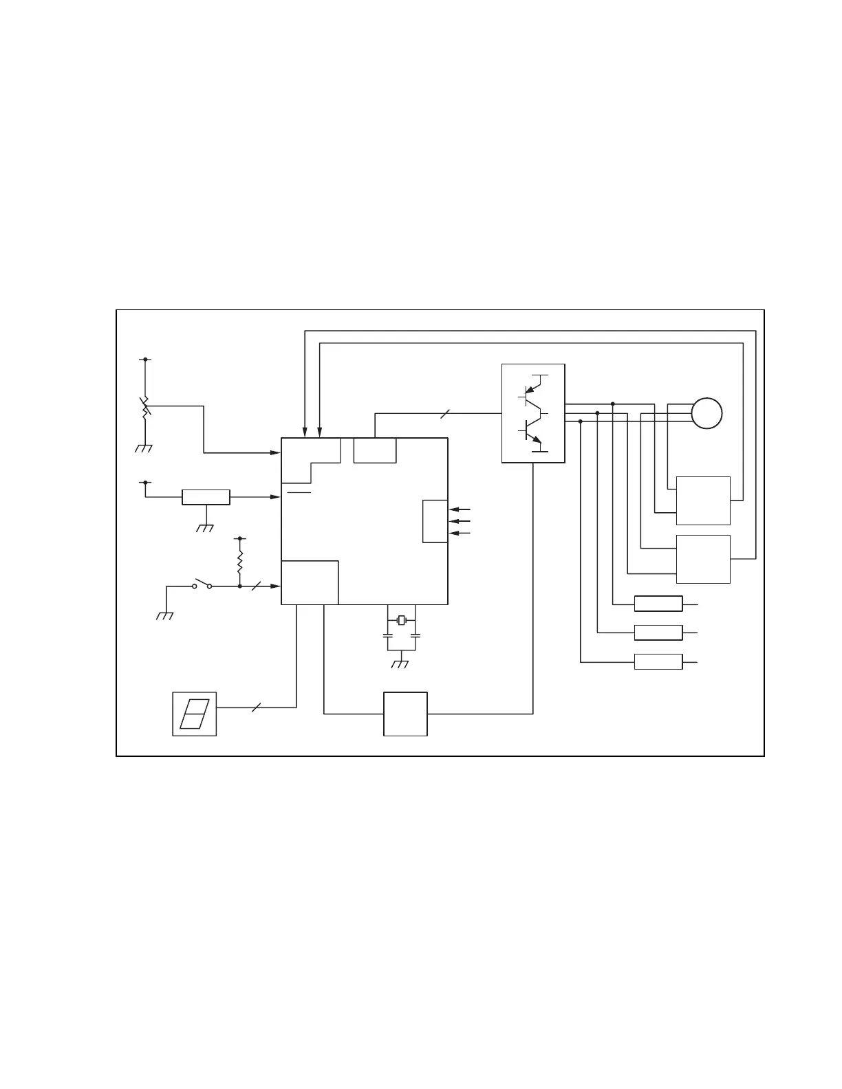
Figure 2-1. Overall System Configuration
Reset circuit
Position
detection
V-U
V-V
V-W
LED display
Revolution
specification SW
3
6
13
A/D converter
Volume for
speed control
Driver IC
Timer
Interrupt
RESET
Port
Microcontroller
V-U
V-V
V-W
M
Current voltage
conversion
WDT
Current voltage
conversion
Position
detection
Position
detection
 Loading...