Application Note U17209EJ1V0AN
31
CHAPTER 3 SOFTWARE CONFIGURATION
3.1 Control Block
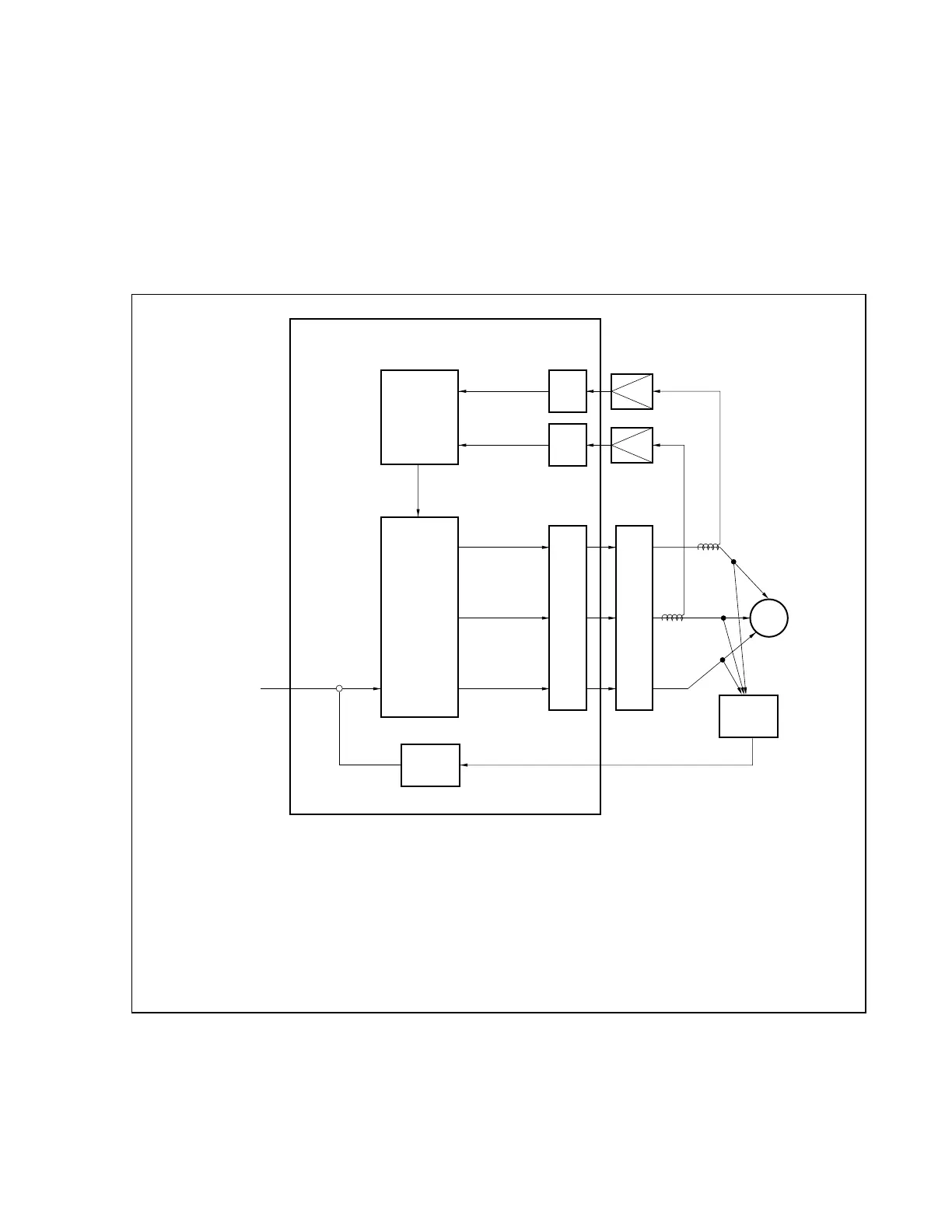
Figure 3-1 shows a diagram of the software control block of the reference system.
Figure 3-1. Diagram of Software Control Block of Reference System
−
iu
iv
u
u, v, w
w
v
A/D
conver-
sion
A/D
conver-
sion
PWM
conver-
sion
Motor
Driver
circuit
<1>
Target
speed
(volume)
<2>
+
<3>
Speed
control
Speed
detection
External
zero-cross
point
detection
<4>
<5>
<6>
Control by microcontroller
<7>
Current
monitor
<1> The volume is loaded by the A/D converter as a target speed.
<2> The speed to be calculated is determined by the difference from the present speed.
<3> Values of phases U, V, and W are set.
<4> The zero-cross point is detected by an induced voltage (by hardware).
<5> The speed is calculated by the interval of zero-cross point in each phase.
<6> An overcurrent is detected by the A/D converter.
<7> The speed is controlled by a current value.
 Loading...