CHAPTER 1 CONTROL METHOD
Application Note U17209EJ1V0AN
14
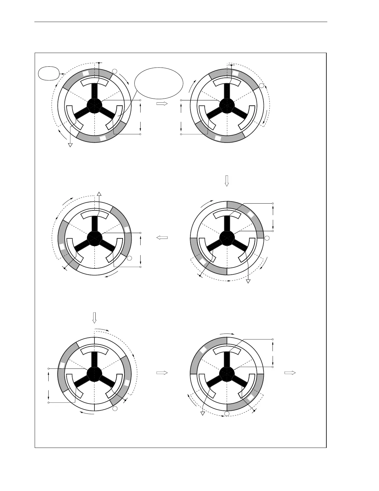
Figure 1-2. Rotor Position Detection Principle
Return to (a)
(a) Rotor position <1> … U-phase stator: S pole
V-phase stator: N pole
W-phase stator: Center point
(b) Rotor position <2> … U-phase stator: S pole
V-phase stator: Center point
W-phase stator: N pole
A
S
S
N
N
V
WC
= 0
V
CC
W-phase stator
is located in the
center of the N pole
and S pole of a
magnet rotor
Magnetic
flux
V
W
U
A
S
S
N
N
V
VC
= 0
V
CC
W
V
U
(d) Rotor position <4> … U-phase stator: N pole
V-phase stator: S pole
W-phase stator: Center point
(c) Rotor position <3> … U-phase stator: Center point
V-phase stator: S pole
W-phase stator: N pole
A
U
S
S
N
N
V
UC
= 0
V
CC
V
W
A
U
S
S
N
N
V
WC
= 0
V
CC
V
W
(e) Rotor position <5> … U-phase stator: N pole
V-phase stator: Center point
W-phase stator: S pole
(f) Rotor position <6> … U-phase stator: Center point
V-phase stator: N pole
W-phase stator: S pole
W
V
U
A
S
S
N
N
V
VC
= 0
V
CC
S
S
N
N
A
U
V
W
V
CC
V
UC
= 0
 Loading...