CHAPTER 3 SOFTWARE CONFIGURATION
Application Note U17209EJ1V0AN
35
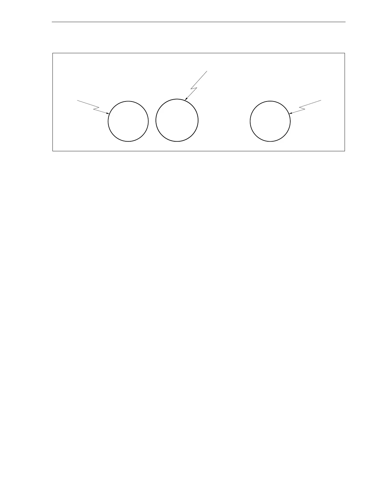
Figure 3-3. Interrupt Processing Structure
(a) Motor control processing (b) Control pin selection processing (c) Wait timer processing
Motor control
processing
50 s interval interrupt
µ
U, V, W change
interrupt
Control pin
selection
processing
Wait timer
processing
10 ms interval interrupt
The status of the operation mode switch is monitored by the main processing, and processing is transferred to CW,
CCW, and stop status. The motor is controlled in the specified status by using a 50
µ
s interval interrupt.
There are the following three motor control statuses.
• Stop status
The motor is not controlled.
• Initial operation status
Estimated revolution control is performed up to the speed at which the zero-cross point of electromotive force can
be detected.
• Speed control status
Feedback revolution control is performed so that the indication speed is attained.
 Loading...