en
4 Startup
⇒ Remove the equipment and accessories from the package.
⇒ Check the delivery for completeness (compare with the scope of delivery).
Required batteries (2x AA) are not included in the scope of delivery.
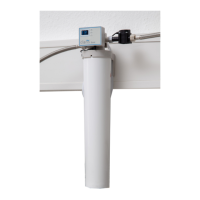
4.1 Installing the lter system
Only use the hoses and adapters provided.
A shut-o valve, e.g., a water faucet, must be installed upstream of the lter system.
Theltersystemcanalsobeoperatedeitherfree-standingoronitssidewithoutbeingsecured.
Verticalwallmountingisrecommended.
⇒ Before the lter system is put into operation, the consumer unit supplied must be free from limescale.
⇒ Determine a suitable location for installing the lter system:
- The location of the system must be frost-proof and protected against direct sunlight.
- There must be sucient space under the lter head for installation of the lter cartridge.
► Determining carbonate hardness
⇒ Briey immerse the test strips (1 sec.).
⇒ Gently shake o excess liquid from the test strip.
⇒ Read the result after 1 minute:
⇒ Determine the blend level in accordance with the table.
Test strips
Result
4x green 1x red 2x red 3x red 4x red
Blend level 3 3 2 2 1
Capacity
Filter cartridge M in
liters
3570 3060 1440 990 510
Capacity
Filter cartridge L in
liters
6670 5710 2690 1840 940
► Setting the blend level
⇒ Press the key (9, Fig. 2) for blending adjustment and turn the blending adjustment dial to the corre-
sponding level (Fig. 2).
⇒ Remove the blending adjustment key after setting has been completed and store the key in a safe place
for possible future adjustments to the settings.
► Assembling the lter head
When assembling the sensor unit, the adapter and the water hoses, make sure that you use the
corresponding gaskets.
⇒ Screw one adapter (13) onto the inlet of the lter head (3, Fig. 1).
⇒ Securely attach the lter head to a wall in a vertical position using appropriate screws (not included in
the scope of delivery).
⇒ Screw one adapter (13) onto the connection of the sensor unit (10)
⇒ Screw the sensor unit (10) to the outlet of the lter head (4, Fig. 1) using the union nut.
⇒ Disconnect the POWER steamer 2 from the power source.
⇒ Turn o the water supply to the POWER steamer 2 and disconnect the water hose to the POWER
steamer 2 from the water supply.
⇒ Connect the water hose for the POWER steamer 2 to the adapter of the sensor unit.
The sensor unit must not be exposed to any mechanical loads.
⇒ Connect the water hose provided to the adapter at the inlet of the lter head and to the water supply.
⇒ Note the ow direction – markings on the lter head and sensor unit!
⇒ Max. torque 10 Nm.
Fig. 6: Typical installation example
- 3 -