en
► Rinsing the lter cartridge
⇒ Run the ushing hose into a suitable container (e.g., a bucket) or into a drain.
⇒ Open the purge valve (5) (OPEN, Fig. 3).
⇒ Turn on the water supply.
Waterescapesfromtheushinghoseassoonastheltercartridgehasbeeninserted!
⇒ Insert the lter cartridge into the lter head.
InserttheltercartridgewithitsmarkingatinsertionmarkA(Fig.5)andscrewitinasfarasitwill
go,operatingmarkB(Fig.5).
⇒ Vent and rinse the lter cartridge.
- Filter cartridge M: Flush with min. 5 liters of water
- Filter cartridge L: Flush with min. 10 liters of water
⇒ Close the purge valve (5) (CLOSE, Fig. 4).
⇒ After the initial installation of the lter system, vent and ush the water drain hose and the POWER
steamer 2 with at least 2 liters of water. To do this, open the service opening on the POWER steamer 2
and run the rinsing program 3 times (see operating instructions for the POWER steamer 2).
After installing the system and inserting or replacing a lter cartridge, check all components for
leak-tightness. Water must not leak out at any location.
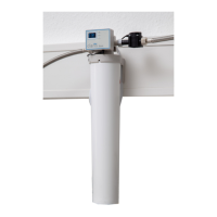
4.2 Installing the programming and display unit
Tooperatetheprogramminganddisplayunit,youwillneed2batteries(typeAA).Thesearenot
includedinthescopeofdelivery!
The programming and display unit can either be attached to the lter head (2)
of the lter unit using the holder (11) or to a wall using the wall bracket provid-
ed (12).
⇒ Push the holder (11) onto the lter head (2) until it snaps into place.
or
⇒ Screw the wall bracket securely to a wall using suitable at-head screws,
max. shank diameter 4 mm, or with the adhesive pads on the back.
⇒ Open the battery compartment and insert batteries, 2x type AA.
⇒ Pay attention to correct polarity.
⇒ Hang the programming and display unit in the holder.
⇒ Insert the connection cable of the sensor unit into the port (20).
In the case of assembly using the wall bracket, the connection cable can be
pressed into the cable guide (21) to prevent the connection plug from being
unintentionally pulled out.
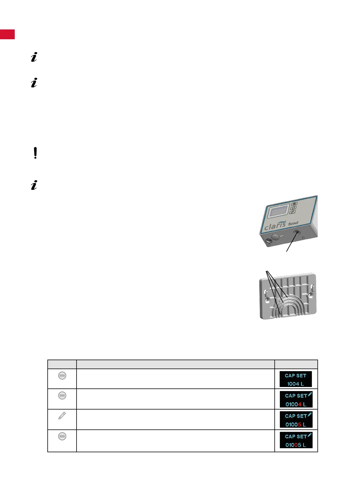
4.2.1 Entering the lter capacity / resetting the counter
⇒ Determine the capacity of the lter cartridge used for the local carbonate hardness (see table in the
installation section).
⇒ Enter the capacity:
Key Display
Press the "MENU" key until CAP SET is shown.
- Display: Set lter capacity.
Press and hold the "MENU" key for approx. 5 seconds.
- The active digit ashes.
Press the "MODIFY" key:
- Set the active digit.
Press the "MENU" key:
- Conrm the active digit and move to the next digit.
- The active digit ashes (repeat the procedure until the last digit).
20
21
- 4 -