NC4+ Blue non-contact tool setting system installation guide
3.12
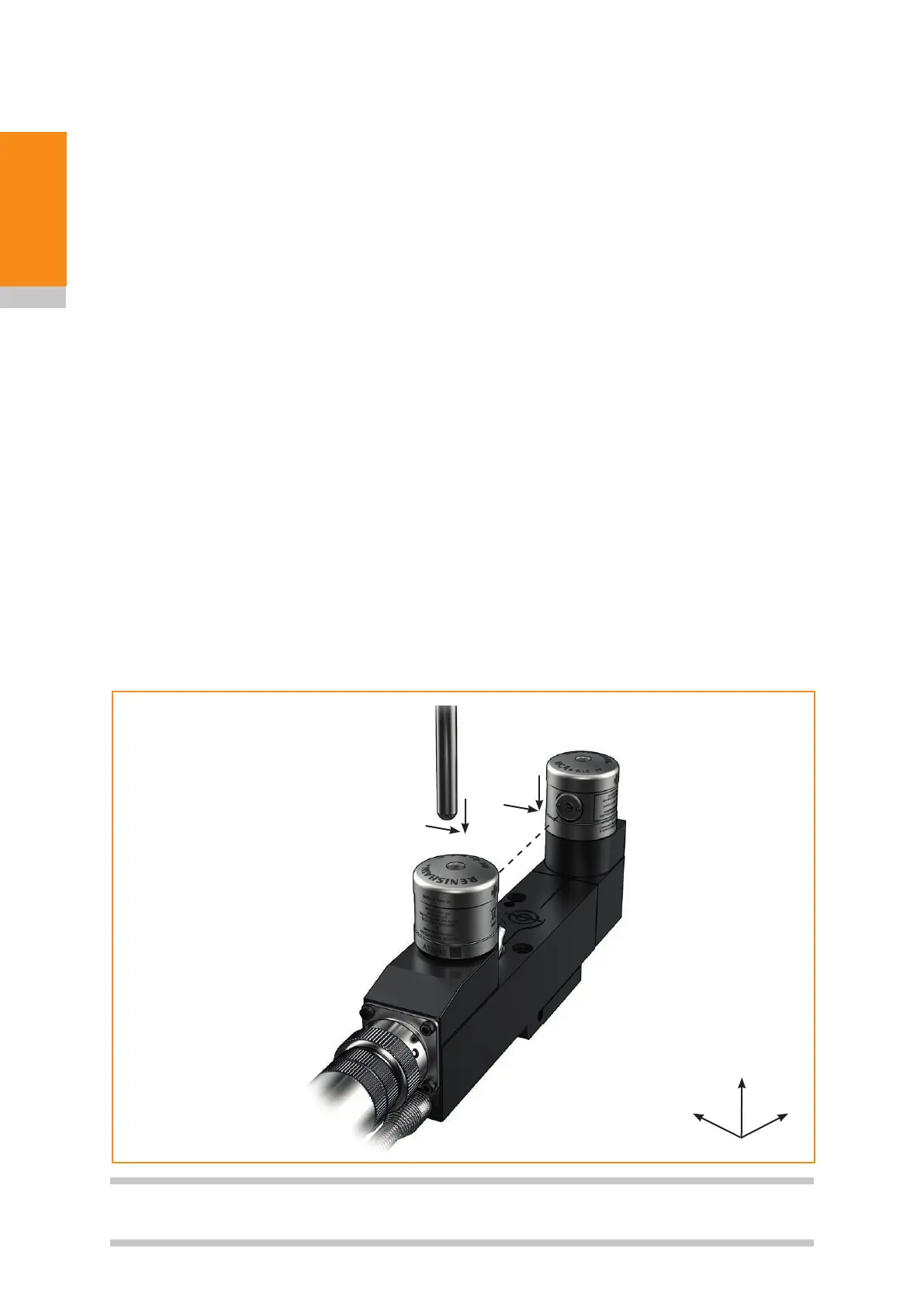
System
installation
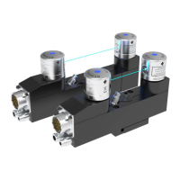
P1
P2
Spindle axis
Beam
axis
Radial
axis
Aligning to the Z-axis
a. Slacken the Z-axis locking screw(s).
b. Adjust the Z-axis adjusting screw(s).
c. Carefully tighten the Z-axis locking screw(s), taking care not to move the unit.
3. After aligning the system, run the beam alignment macro again.
Alignment tolerances
The tolerances to which a tool can be set are dependent on the parallelism of the laser beam to the
machine axes.
Tool setting applications
Over a span of 100 mm (3.94 in), the following alignment accuracies are easily achievable:
Spindle axis (P2 – P1): ≤ 10 µm (0.39 µin)
Radial axis (P2 – P1): ≤ 1 mm (0.39 in)
These values are sufficient for the majority of tool setting applications.
Tool breakage detection applications
Over a span of 100 mm (3.94 in), the following alignment accuracies are easily achievable:
Spindle axis (P2 – P1): ≤ 0.2 mm (0.008 in)
Radial axis (P2 – P1): ≤ 1 mm (0.39 in)
These values are sufficient for the majority of tool breakage applications.
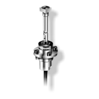
NOTE: For best measurement performance, Renishaw recommends calibrating NC4+ Blue systems
using a ball-nosed cylinder-type calibration tool.
 Loading...