4.9
Maintenance
10. At the transmitter unit, refit the cover then refit and tighten the cover securing screw.
11. Check that the laser beam is not obstructed.
On the interface unit, set switch SW1-2 (NC set-up) to ‘Off’.
Check that:
• the interface status LED is green, and
• the voltmeter reading is between 4.7 V and 5.4 V.
NOTE: If the set-up tool is used, ignore the reading on the display. A false reading is shown when
the NC set-up mode is switched off.
12. If the beam is blocked when the switch is set to ‘Off’, the system will be unable to set itself
correctly. If this occurs, remove the obstruction then set switch SW1-2 (NC set-up) to ‘On’ then
back to ‘Off’.
Using a voltmeter
A standard voltmeter, that is within calibration, may be used for setting up and aligning the NC4+ Blue
system.
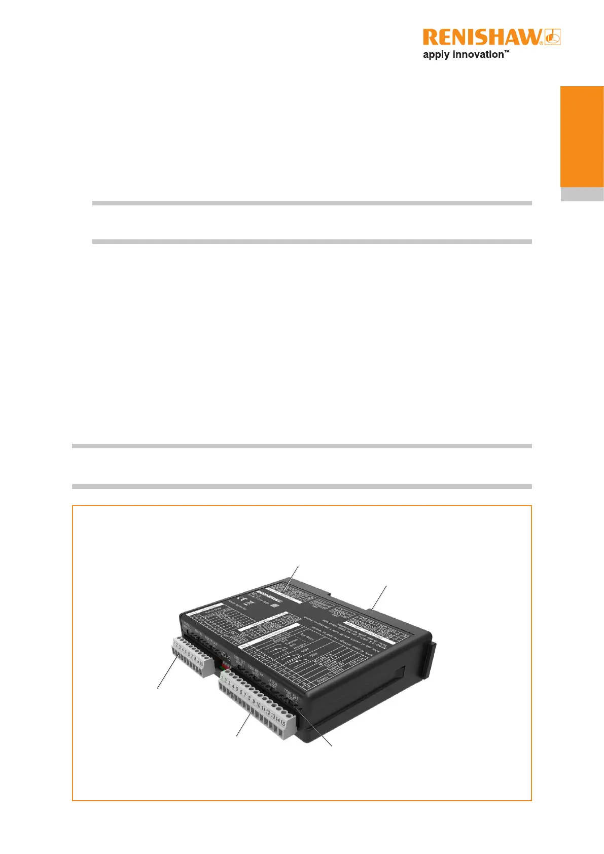
1. Position the voltmeter next to the receiver unit. Connect a wire between terminal CN1-1 on the
NCi-6 interface unit and one of the voltmeter probes. Connect a second wire between terminal
CN1-2 and the other voltmeter probe.
2. On the interface unit, set switch SW1-2 (NC set-up) to ‘On’.
NOTE: If a negative reading is obtained when you use the voltmeter, swap over the voltmeter probe
connections.
Diagnostic LEDs
Connector
CN2 (15-way)
Connector
CN1 (10-way)
Removable cover
Top face interface label


 To Next Page