AligningtheMCR20NIandMCR20totheCMMaxes
AligningtheMCR20NIorMCR20totheCMMaxes
It is recommended that the rack is approximately aligned to the CMM axis using the procedure below before
using the UCCserver set up wizard.
WARNINGS: The use of eye protection is recommended.
Under certain circumstances, the probe signal may falsely indicate a probe seated condition. Do not rely
on probe signals to stop the machine.
NOTES: For the stylus being used, the length (L) must be either 20 mm or 30 mm and the appropriate
ball radius (R) must be used to calculate offsets.
It is strongly recommended that the EM1 STD and EM2 STD probe extension modules are not used for
datuming of the MCR20NI or MCR20, as the extended probe length may lead to increased concentricity
errors within the probe system.
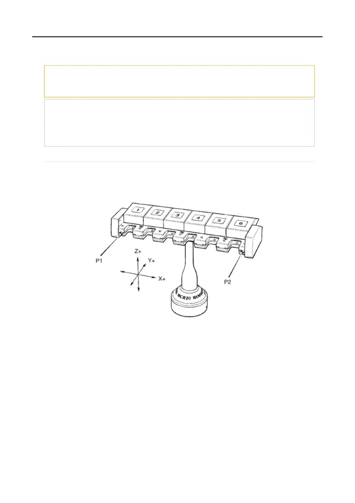
1. Latch all the port lids in their open positions by pushing each lid fully open and engaging the locking
pegs into the slots in the docking plate.
2. Take points P1 and P2.
3. Using the appropriate allen key, fully release the grubscrew(s) within the base of the MCR20NI or
MCR20.
4. Adjust the orientation of the rack until the runout between points P1 and P2 is less the 0.25 mm.
Retaining the rack in this postion retighten the grubscrew.
Pa
e 65 of 73PH20 user's
uide
19/12/2012file://C:\TEMP\~hh906A.htm