Summary of probe module changing procedure
Operation X-axis Y-axis Z-axis
Safe clearance position for port
(n)
Xn Ys Z
Move to docking position * Y *
Release probe module * * Zr
Move to retract point (RP) * Yr *
Select next port (n) Xn * *
Enter port * Y *
Move to docking position * * Z
Move to safe clearance position * Ys *
Xn = X1 to X6 as selected by the user
Ys = Y – 100 mm
Zr = Z + 3 mm
Yr = Y – 17.2 mm
* = No change to the previous setting of the axis register
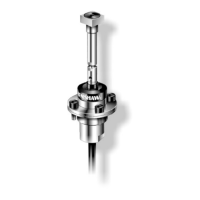
Using the MSR1 module storage rack
The location points for the TP20 probe modules are positioned approximately below the numbered labels on the rack. Accurate positioning is
not necessary, as the magnetic force will pull them into the correct position.
The probe modules are held magnetically in the MSR1 and can be rotated if required.