7
en
Connect the RCTT Remote control (accessory) to the following terminals:
7 GND RCTT Remote control
8 Switching input RCTT Remote control
9 Signal LED output RCTT Remote control
Connect the VBus
®
to the terminals marked VBus with either polarity:
13 VBus terminal
14 VBus terminal
The mains connection is at the following terminals:
25 Neutral conductor N
27 Conductor L
15 Protective conductor ⏚
The controller comes with the following cable links pre-connected:
24 Link from the neutral conductor to terminal 21
26 Link from the conductor L to terminal 23
2.3 Grundfos Direct Sensor
TM
The controller is equipped with 1 input for a digital VFD Grundfos Direct Sensor™
for measuring the ow rate and the temperature. Connection is made at the VFD
terminal (bottom left).
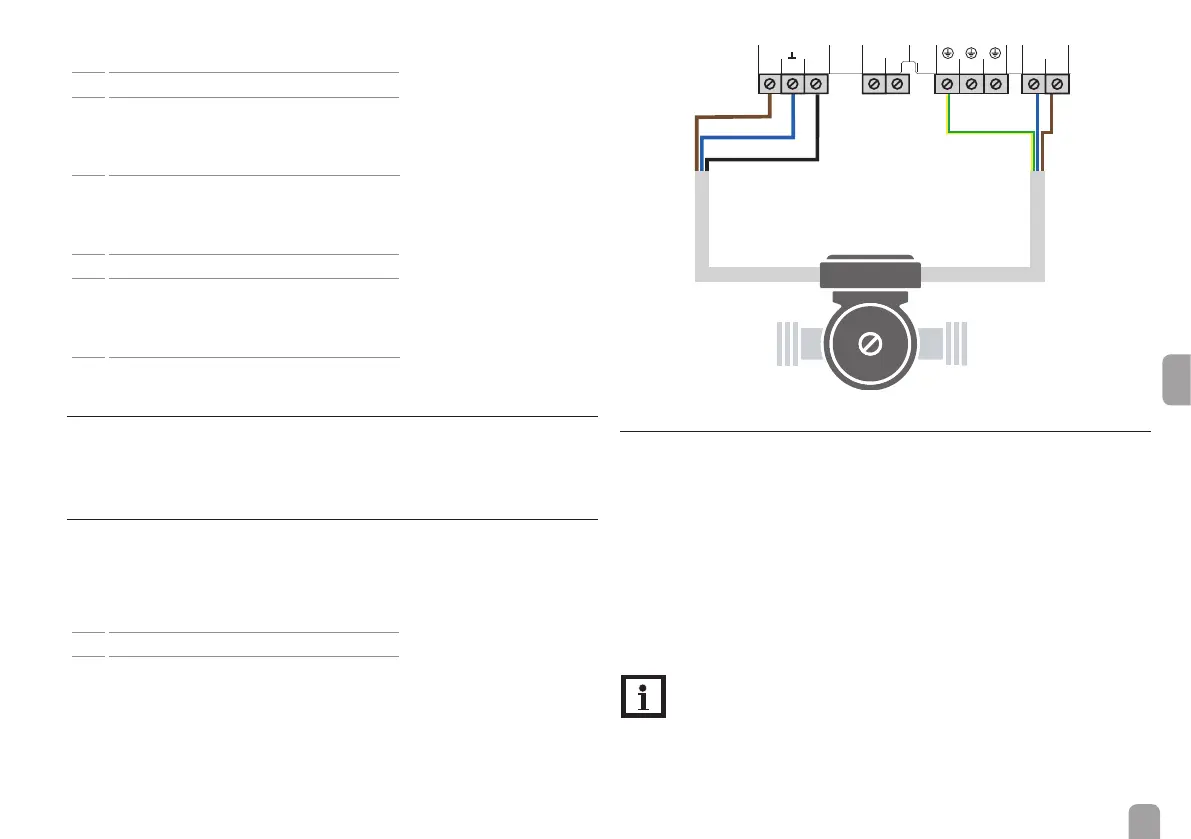
2.4 PWM interface
Speed control of a HE pump is possible via a PWM signal. The pump has to be
connected to the relay as well as to the PWM output of the controller. Power is
supplied to the HE pump by switching the corresponding relay on or off.
The terminal marked PFB is an interface for a bidirectional HE pump.
10 PWM output, control signal
11 PWM, GND
12 PWM input, feedback signal
VBus
10
11
12
13 14
PW
PFB
N
17
18
19
1615
R1
2.5 Data communication / Bus
The controller is equipped with the VBus
®
for data transfer and energy supply to
external modules. The connection is to be carried out at the terminals marked
VBus (any polarity). One or more VBus
®
modules can be connected via this data
bus, such as:
• SD3 smart Display / GA3 Large Display
• DL2 / DL3 Datalogger
• KM2 Communication module
Furthermore, the controller can be connected to a PC or integrated into a net-
work via the VBus
®
/USB or VBus
®
/LAN interface adapter (not included). Different
solutions for visualisation and remote parameterisation are available on the web-
site www.resol.com.
Note
More accessories on page 37.
brown
230 V~ power
supply
pump power supplypump signal input
PWM signal cable
black (optional)
brown
blue
blue
green/yellow