en
5
Installation
CommissioningSettingsTroubleshooting
Accessories
Display
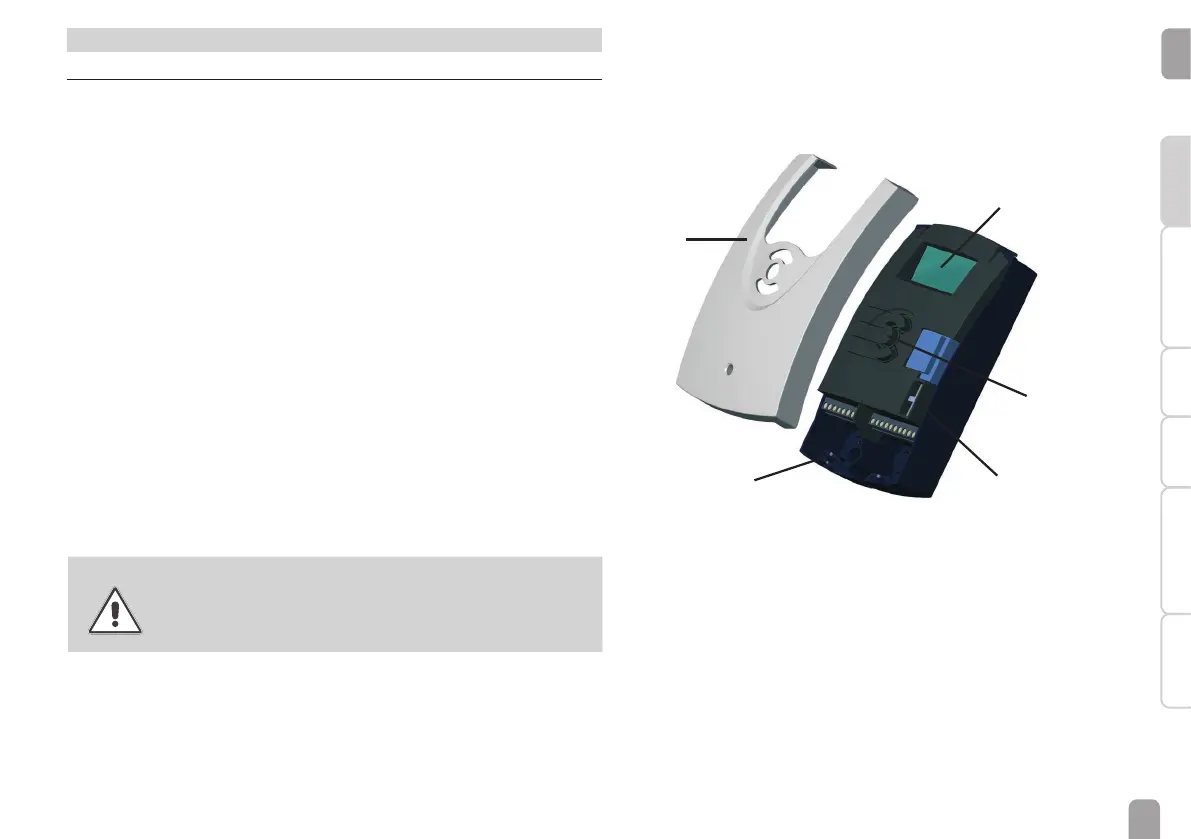
1 Installation
1.1 Mounting
The unit must only be installed
• in a dry interior location
• in a non-hazardous location
• not close electromagnetic fields
The controller must additionally be supplied from a double pole switch with contact
gap of at least 3 mm [0.12"] .
Route sensor cables and power supply cables separately.
Î Unscrew the crosshead screw of the front cover and remove the cover by
pulling it downwards
Î Mark the upper fastening point on the wall and drill
Î Fasten one of the enclosed wall plugs and screw leaving the head protruding
Î Hang the housing at the upper fastening point
Î Mark the lower fastening point through the hole in the terminal box (centres
130 mm)
Î Drill and insert the wall plug
Î Hang the housing at the upper fastening point, fasten it to the wall with the
fastening screw and tighten
Î Complete wiring connections in accordance with terminal allocations, see
chap.1.2 “Electrical connection”
Î Put the cover on the housing
Î Fasten the cover by means of the cross-head screw
WARNING!
Electric shock!
Upon opening the housing, live parts are exposed!
Î Always disconnect the controller from power supply
before opening the housing!
display
push buttons
fuse
cable conduits with
strain relief
cover

 Loading...


