en
6
Installation Commissioning Settings AccessoriesTroubleshooting
Display
1.2 Electrical connection
WARNING!
Electric shock!
Upon opening the housing, live parts are exposed!
Î Always disconnect the controller from power supply
before opening the housing!
Note:
Connecting the device to the mains supply must always be the last step of
the installation! The power supply of the controller must be carried out via
an external power switch.
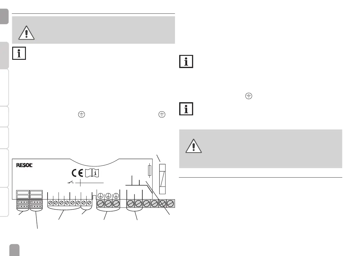
The supply voltage must be 100 ... 240 V~ (50 ... 60 Hz) . The controller is equipped
with 2 relays in total to which loads such as pumps, or a mixer, etc. can be connected:
Relay 1 Relay 2
18 = conductor R1 16 = conductor R2
17 = neutral conductor N 15 = neutral conductor N
11 = protective earth conductor
12 = protective earth conductor
Connect the VBus
®
to the terminals marked “VBus” with either polarity.
The terminals marked PWM1/2 are control outputs for high-efficiency pumps.
Connect the temperature sensors (S1 to S4) to the following terminals with
either polarity:
S1 = Sensor 1 (sensor SFB / stove)
S2 = Sensor 2 (sensor store base)
S3 = Sensor 3 (sensor store top)
S4 = Sensor 4 (system-dependent)
Note:
In order to connect sensor 4 to the controller, a sensor adapter cable is
required, see page 33.
The mains connection is at the terminals:
19 = neutral conductor N
20 = conductor L
13 = protective earth conductor
Note:
If no indication is made on the display, the fuse may be blown. Replace it
with the spare fuse included with the device. For this purpose, pull the fuse
holder from the base.
WARNING!
ESD damage!
Electrostatic discharge can lead to damage to electronic compo-
nents!
Î Take care to discharge properly before touching the
inside of the device! To do so, touch a grounded sur-
face such as a radiator or tap!
1.3 Data communication / VBus
®
The controller is equipped with the RESOL VBus
®
for data transfer and energy
supply to external modules. The connection is to be carried out at the two termi-
nals marked VBus and GND (any polarity).
One or more RESOL VBus
®
modules can be connected via this data bus, such as:
• DL2 Datalogger
• DL3 Datalogger
• VBus
®
/ USB or VBus
®
/ LAN interface adapters
• AM1 Alarm module
• SDFK
VBus
®
mains terminals
load terminals
sensor terminals
PWM terminals
Connection
sensor 4
protective earth
conductor terminal
1 (1) A 240 V~
1 (1) A 240 V~
R1
R2
Made in Germany
DeltaTherm
®
FK
Temp. Sensor Pt1000
S2S1 S3 VBus
11 12 13
T2A
100 ... 240 V~
50-60 Hz
LN
R1
NNR2
2019
18
171615
S4
—
—
PWM1/2
Fuse
 Loading...


