Falk Quadrive Shaft Mounted Drives Model A • Owners Manual
Sizes 5107-5315 (Page 19 of 52)
Rexnord (PN-2128394) 378-200
3001 W. Canal St., Milwaukee, WI 53208-4200 USA January 2019
Telephone: 414-342-3131 Fax: 414-937-4359 www.rexnord.com Supersedes 04-17
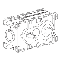
4. INTERMEDIATE SHAFT ASSEMBLY — Ref. #2A
Assembly - Type J09, J14 and J25 - Figure 22. Prepare
bearings per Steps 1b and c on Page 18.
a. ALL SIZES — Heat gear Ref. #1A4 to 325°F (163°C)
in an oven. Insert key, Ref. #2A4, in shaft keyway.
Assemble gear onto shaft, with the chamfer toward
pinion, using a press to ensure a tight fit. Allow
gear to cool before proceeding.
b. Assemble spacer, Ref. #2A6, onto intermediate
shaft (except sizes 5307 and 5315). Seat bearings
or cones, Ref. #2A1 & 2A2, on shaft. Seat all
components firmly so spacers do not rotate on
shaft.
CAUTION: Allow assembly to cool. Apply a coat
of oil to the cooled bearings to lubricate and avoid
scoring of the working surfaces.
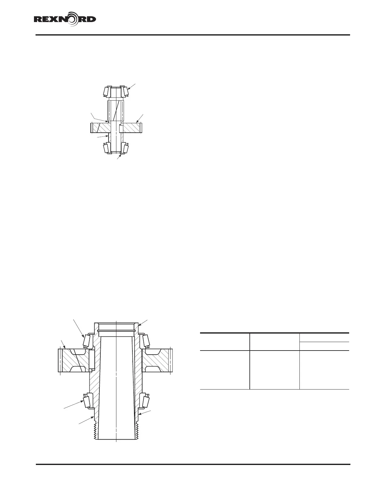
5. LOW-SPEED SHAFT ASSEMBLY — Ref. #4A
Assembly - ALL TYPES - Figure 23. Prepare bearing
cones per Steps 1b and c.
a. Heat gear, Ref. #4A4, to 325°F (163°C) in an
oven. Insert gear key, Ref. #4A5, into hollow shaft
keyway. Assemble the gear with the chamfer
toward the shoulder on the shaft using a press to
ensure a tight fit.
WARNING: Exercise care so that the gear keyway
does not contact the shaft seal diameter(s) as
scoring could occur.
b. Seat bearing cones, Ref. #4A1 & 4A2, firmly
against gear and shoulder.
CAUTION: Allow assembly to cool before
proceeding. Apply oil to the cooled bearing rollers
and gear teeth to lubricate and avoid scoring of
the working surfaces.
6. BEARING ADJUSTMENT
a. SIZES 5107 THRU 5315 — Bearing adjustment is
made by adjusting thickness of metal shims, Ref.
#24, behind bearing cups in input housing, Ref.
#10.
NOTE: The thickest shim should be located
adjacent to the bearing cup. The thinnest shims
should be located in the center of the shim pack.
(1) Support input housing, such that when high-
speed shaft assembly, Ref. #1A or 3A, is
lowered into place there is clearance for shaft
extension end. Install bearing cups in input
housing without any metal shims. Tap dowel
pins into input housing with solid pin nearest
high-speed shaft bore.
(2) Lower low-speed shaft assembly, Ref. #4A,
into input housing, Ref. #10, with threaded
end facing up (DO NOT install Ref. #1A [or 3A]
or 2A shaft assemblies at this time).
(3) Assemble output housing, Ref. #11, to input
housing. Install housing flange fasteners, Ref.
#25, with heads of cap screws against input
housing. Cross tighten fasteners to torque
specified in Table 14.)
(4) Measure low-speed shaft axial float with a
dial indicator, in accordance with method
described on the following page.
4A1 BEARING
4A4 GEAR
4A2 BEARING
4A3 HOLLOW SHAFT
SHAFT SEAL
DIAMETER
SHAFT SEAL
DIAMETER
Figure 22
2A1 BEARING
1A4
GEAR
2A5 SPACER
2A6 SPACER
2A2 BEARING
Figure 23
TABLE 14 — Housing Flange Fastener Size &
Tightening Torque ±5%
(Non-Lubricated Fasteners)
DRIVE SIZE Fastener Size
Tightening Torque
lb-ft (Nm)
5107 .312-18 19 (26)
5115 .312-18 19 (26)
5203 .375-16 27 (37)
5207 .500-13 67 (91)
5215 .500-13 67 (91)
5307 .500-13 67 (91)
5315 .500-13 67 (91)
 Loading...