Owners Manual • Falk Quadrive Shaft Mounted Drives Model A
(Page 4 of 52) Sizes 5107-5315
378-200 (PN-2128394) Rexnord
January 2019 3001 W. Canal St., Milwaukee, WI 53208-4200 USA
Supersedes 04-17 Telephone: 414-342-3131 Fax: 414-937-4359 www.rexnord.com
Section I
DRIVE INSTALLATION
OUTFITTING
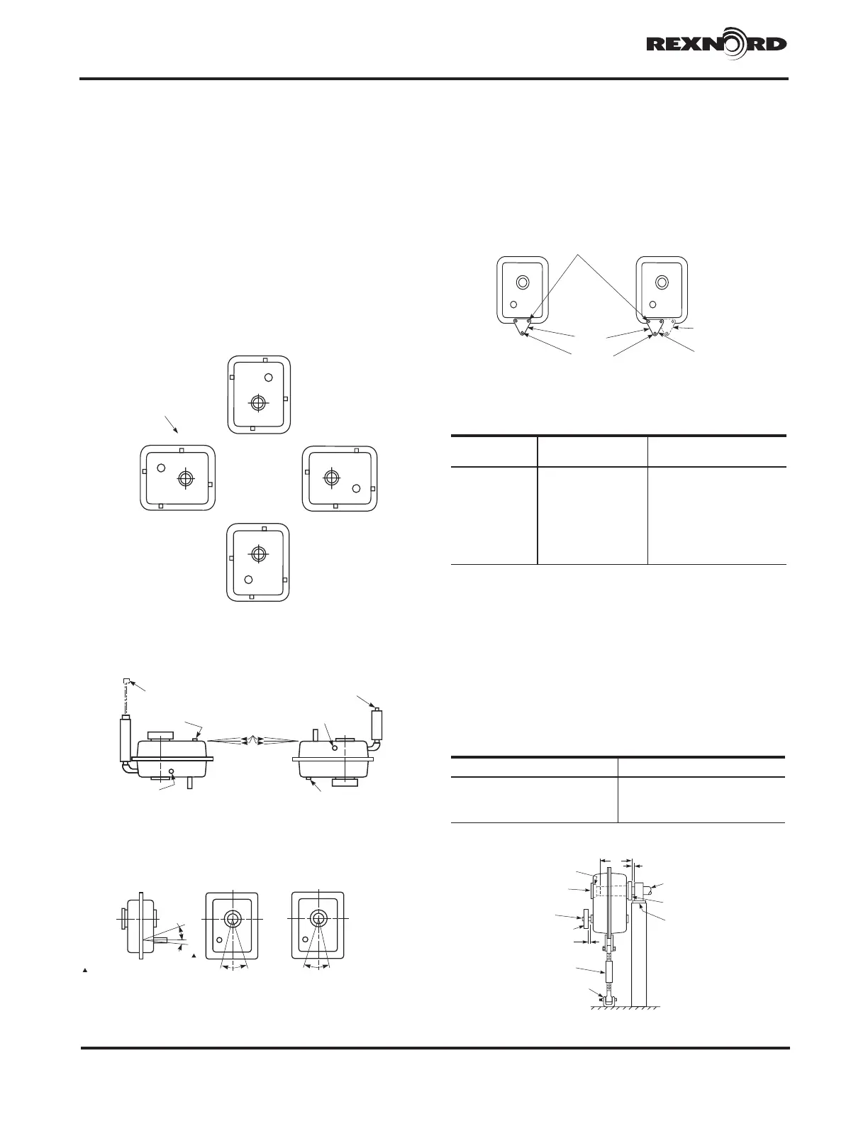
1. JR, JF, & JSC — Find the desired mounting position
in Figure 1 and install air vent and magnetic drain plug
(packaged separately with basic drive). Also note and/
or mark the oil level plug location OR in the case of a
vertical mounting, refer to Appendix E for installation
of vertical stand pipe. If the mounting angle exceeds
the limitations shown in Figure 1, refer to Appendix F
to determine modifications necessary within the limits
illustrated therein. DO NOT fill drive with lubricant at
this time. Oil plugs are located on input housing half.
2. JR — Remove anchor brackets, housing flange fasteners
and rod end fasteners from tie rod kit and assemble
to drive as illustrated in Figure 2. Refer to Table 1 for
tightening torque (original fasteners may be discarded).
FILL
DRAIN
OIL LEVEL
STANDPIPE &
VENTED DIPSTICK
FILL VENT &
STANDPIPE
INPUT SHAFT DOWN
INPUT SHAFT UP
DRAIN
± 1° MAX
12 O’ CLOCK
D
L
F
F
L
D
3O’CLOCK
F
L
D
6O’CLOCK
F
L
D
9O’CLOCK
SIZES 5203 THRU 5315
5:1 RATIO ONLY: RELOCATE
AIRVENT ON OUTPUT SIDE
FOR 9 O’CLOCK MOUNTING
REPOSITION PLUGS TO
SUIT REQ’D MOUNTING
D = DRAIN
F = Fill & Vent
L = OIL LEVEL
(HIGHEST INPUT
SIDE PLUG)
10
MAX
°
5°
MAX
30 UP
(20° FOR
5315)
°
5DOWN°
INCLINE ROTATION
5°
MAX
10°
MAX
(5107&5115) (5203 THRU 5315)
0° Incline down on drives
with backstop in 9 or 12
o’clock mounting position.
HORIZONTAL DRIVESFigure 1
VERTICAL DRIVES
ANGULAR LIMITS FOR HORIZONTAL MOUNTING
(ALL CLOCK POSITIONS)
5107&5115 5203 THRU 5315
HOUSING FLANGE
FASTENERS
ANCHOR
BRACKET
TORQUE ARM
FASTENER
ALTERNATE
LOCATION
PREFERRED
LOCATION
Figure 2
TABLE 1 — Housing Flange Fastener Size
and Tightening Torque
(Non-Lubricated Fasteners)
DRIVE SIZE Fastener Size
Tightening Torque lb-ft
(Nm)
5107 .312-18 19 (26)
5115 .312-18 19 (26)
5203 .375-16 28 (37)
5207 .500-13 69 (94)
5215 .500-13 69 (94)
5307 .500-13 69 (94)
5315 .500-13 69 (94)
3. JR — The tapered bore hollow shaft is designed for use
with a TA Taper bushing for mounting on a driven shaft with
a straight outside diameter. Shaft tolerances for the driven
shaft are given in Table 1A. The minimum and maximum
driven shaft engagements, dimension “N” in Figure 3, are
shown in Table 2. The minimum engagement is necessary
for full bushing engagement; the maximum engagement is
only required if a thrust plate will be employed to remove the
drive from the driven shaft (see Appendix C for preferred
removal method).
TABLE 1A — Driven Shaft Tolerances
Shaft Diameter – Inches Maximum Under-size – Inches
Up to 1.500 .004
1.500 - 2.500 incl. .005
2.500 - 4.000 incl. .006
c Millimeters = h10 tolerance.
N
THRUST
PLATE
HOLLOW
SHAFT
COVER
HIGH-SPEED
SHAFT
SHEAVE
MINIMUM SPACE REQUIRED
FOR V-BELT CLEARANCE
TORQUE
ARM
CLEVIS
BRACKET
MINIMUM SPACE REQUIRED
DRIVEN
SHAFT
BUSHING
NUT
BEARING
SUPPORT
Figure 3