Falk Quadrive Shaft Mounted Drives Model A • Appendix C
Sizes 5107-5315 (Page 35 of 52)
Rexnord (PN-2128394) 378-200
3001 W. Canal St., Milwaukee, WI 53208-4200 USA January 2019
Telephone: 414-342-3131 Fax: 414-937-4359 www.rexnord.com Supersedes 04-17
TA Removal Tool
REMOVAL OF QUADRIVE
5. Use a spanner wrench to apply torque through the
input shaft keyway (Type J05 clockwise; Types J09,
J14 or J25 counter-clockwise) to loosen the bushing
nut.
CAUTION: Never use the prime mover to produce the
torque needed. This could result in severe personal
injury or damage to the equipment.
To avoid damage to the drive or the removal tool, DO
NOT exceed the H.S. shaft torque values listed in Table
3. NOTE: The nut will rotate freely for approximately
180° as it moves from the locked to the removal
position. Resistance will indicate that unseating
is occurring. Turn until the nut and bushing are
completely free. Now, prepare the drive for lifting by
disconnecting the torque arm at the drive end.
6. ALTERNATE METHOD — Torque may be applied to
the sheave or sprocket mounted on the input shaft.
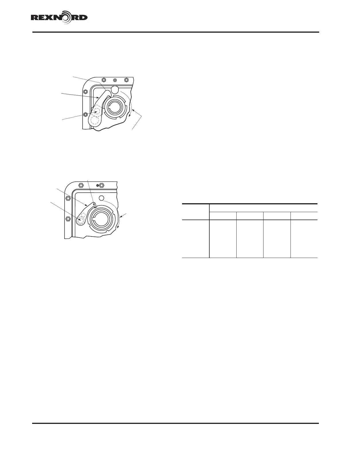
TOOL
SIZES 5107, 5115, 5203, & 5207
LOW-SPEED SHAFT
ROTATION
ENGAGE TOOL
IN SLOT
USE INNER
HOLE
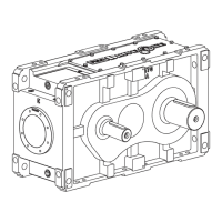
TOOL
ENGAGE TOOL
IN SLOT
SIZES 5215, 5307, & 4315
LOW-SPEED SHAFT
ROTATION
USE OUTER
HOLE
Figure 3
Figure 4
TABLE 3 — Maximum Torque – H.S. Shaft
lb-ft (Nm)
DRIVE
SIZE
Drive Reduction
J05 J09 J14 J25
5107 164 (223) 88 (120) 58 (78) 33 (44)
5115 248 (336) 133 (181) 90 (121) 50 (68)
5203
406 (550) 224 (304) 143 (193) 79 (107)
5207 493 (668) 263 (357) 173 (234) 100 (136)
5215 677 (917) 371(503) 245 (332) 133 (181)
5307 762 (1033) 405 (549) 278 (377) 150 (203)
5315 813 (1102) 432 (585) 283 (384) 160 (217)