Falk Quadrive Shaft Mounted Drives Model A • Appendix J
Sizes 5107-5315 (Page 45 of 52)
Rexnord (PN-2128394) 378-200
3001 W. Canal St., Milwaukee, WI 53208-4200 USA January 2019
Telephone: 513-455-5030 Fax: 414-937-4359 www.rexnord.com Supersedes 04-17
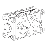
Drive Shaft Recomendations Using TA Taper Bushing
C
D
FURNISHED
BY CUSTOMER
MOUNTING
SURFACE
THRUST
PLATE
FASTENER
MOUNTING
SURFACE
B
A
W(Keyway)
H(Keyway)
L(Keyway)
0.010” (0.25 mm) RMAX.
IN GROOVE CORNERS
F
DB
G
DA
1-S DIA. UNC TAPPED HOLE
T-DEEP
.06” (1.5 mm) RADIUS
TABLE 2 — Thrust Plate Fastener Data
(Non-Lubricated Fasteners)
DRIVE
SIZE
Fastener Size & Grade
Max Tightening
Torque lb-ft (Nm)
Min Thread Depth
Inches (mm)
5107 .500-13UNC x 3.50, GR.8 92 (125) 2.00 (50.8)
5115 .500-13UNC x 4.00, GR.8 92 (125) 2.00 (50.8)
5203 .625-11UNC x 3.50, GR.8 183 (248) 2.00 (50.8)
5207 .625-11UNC x 3.50, GR.8 183 (248) 2.00 (50.8)
5215 .875- 9UNC x 5.00, GR.8 533 (723) 2.50 (63.5)
5307 1.000- 8UNC x 5.00, GR.5 567 (769) 2.50 (63.5)
5315 1.000- 8UNC x 5.00, GR.8 792 (1074) 2.50 (63.5)
c Fasteners may be hex socket head or hex head except for size 5307,
which must be a hex head to clear input end cover.
TABLE 3 — Removal & Backing Bolt Size
and Tightening Torque
DRIVE
SIZE
Removal Bolt Size &
Min Length – Inches
Max Tightening
Torque lb-ft (Nm)
Backing Bolt
Size & Max
Length – Inches
5107 .625-11UNC x 1.75 133 (180) .500-13UNC x 1.25
5115 .625-11UNC x 1.75 133 (180) .500-13UNC x 1.25
5203 .750-10UNC x 2.00 242 (328) .625-11UNC x 1.75
5207 .750-10UNC x 2.00 242 (328) .625-11UNC x 1.75
5215 1.000- 8UNC x 2.50 567 (769) .875- 9UNC x 2.25
5307 1.125- 7UNC x 3.00 742 (1006) 1.000- 8UNC x 2.50
5315 1.125- 7UNC x 3.00 742 (1006) 1.000- 8UNC x 2.50
TABLE 4 — Dimensions for Largest Bore Bushing – Inches (mm)
DRIVE
SIZE
Thrust
Plate
Kit
Thrust
Plate
Part
No.
A
± 0.010
(±0.250)
B
± 0.030
(±0.75)
C
D
DA
DB
Min
Retaining Ring ♣ Keyway ♥
S
T
Min
Groove Spir O Lox
W H
L
Min
F G
Mfg
No.
Max
O.D
5107 TP4107JF 0778773
4.780
(121.41)
5.000
(127.00)
-1.356 (-34.4)
-1.606 (-40.8)
2.500
(63.50)
1.4375
1.750
(44.45)
1.295
1.287
0.056
0.060
RSN-137 1.500 0.375 0.1875
3.563
(90.50)
0.500-13
2.00
(50.8)
5115 TP4115JF 0778774
5.330
(135.38)
5.500
(139.70)
-1.528 (-38.8)
-1.794 (-45.6)
3.250
(82.55
1.9375
2.250
(57.15)
1.735
1.725
0.068
0.072
RST-181 2.000 0.500 0.2500
4.000
(101.60)
0.500-13
2.00
(50.8)
5203 TP4203JF 0778775
5.310
(134.87)
5.625
(142.88)
-1.634 (-41.5)
-1.921 (-48.8)
3.500
(88.90)
2.1875
2.500
(63.50)
1.952
1.940
0.086
0.091
RSN-206 2.250 0.500 0.2500
4.625
(117.48)
0.625-11
2.00
(50.8)
5207 TP4207JF 0778776
5.890
(149.61)
6.250
(158.75)
-1.557 (-39.6)
-1.885 (-47.9)
4.000
(101.60)
2.4375
2.750
(69.85)
2.290
2.278
0.056
0.060
RS-236 2.500 0.625 0.3125
5.625
(142.88)
0.625-11
2.00
(50.8)
5215 TP4215JF 0778777
6.860
(174.24)
7.125
(180.98)
-1.755 (-44.6)
-2.082 (-52.9)
4.750
(120.65)
2.9375
3.250
(82.55)
2.728
2.716
0.056
0.060
RS-281 3.062 0.750 0.3750
5.875
(149.22)
0.875-9
2.50
(63.5)
5307 TP4307JF 0778778
7.170
(182.12)
7.500
(190.50)
-1.843 (-46.8)
-2.175 (-55.2)
5.125
(130.18)
3.4375
3.750
(95.25)
3.172
3.160
0.103
0.108
RSN-334 3.625 0.875 0.4375
6.750
(171.45)
1.000-8
2.50
(63.5)
5315 TP4315JF 0778779
7.700
(195.58)
8.000
(203.20)
-1.840 (-46.7)
-2.175 (-55.2)
6.000
(152.40)
3.9375
4.250
(107.95)
3.701
3.690
0.120
0.125
RST-387 4.125 1.000 0.5000
7.062
(179.37)
1.000-8
2.50
(63.5)
Figure 1
c For metric drive shafts or bushing bores smaller than the maximum provide the retaining ring groove per manufacturers’ recommendations, keyway
appropriate for the shaft diameter, and DB minimum of 0.300” (7.62 mm) larger than the bushing bore to provide adequate backing.
Kit consists of: thrust plate, thrust plate fastener, hollow shaft retaining ring, and drive shaft retaining ring.
The range for C dimensions is the variation which may occur due to axial compression and manufacturing tolerances. Negative C dimensions indicate that
the bushing protrudes beyond the mounting surface.
The D dimension is the recommended minimum bore which clears the TA Taper bushing flange.
44 Shaft diameter tolerances are per AGMA as follows: to 1.50” = +.000”, -.004”; over 1.50” to & including 2.50” = +.000”, -.005”; over 2.50” to & including
4.00” = +.000”, - .006”. Metric drive shafts are to be based on h10 tolerances.
w Smalley retaining rings may be used instead of Spir O Lox by substituting WS for RS. WST for RST or WSM for RSN.
y Inch keyway width tolerances are as follows: over .312” to & including .500” = +.0025”, -.0000”; over .500” to & including 1.000” = +.0030”, -.0000”. Metric keyway
widths are based on class N9 tolerances. Inch keyway depth tolerance is +.010”, -.000”. Refer to ISO 773 or DIN 6885 sheet 1 for metric keyway depth tolerances