Owners Manual • Falk Quadrive Shaft Mounted Drives Model A
(Page 6 of 52) Sizes 5107-5315
378-200 (PN-2128394) Rexnord
January 2019 3001 W. Canal St., Milwaukee, WI 53208-4200 USA
Supersedes 04-17 Telephone: 414-342-3131 Fax: 414-937-4359 www.rexnord.com
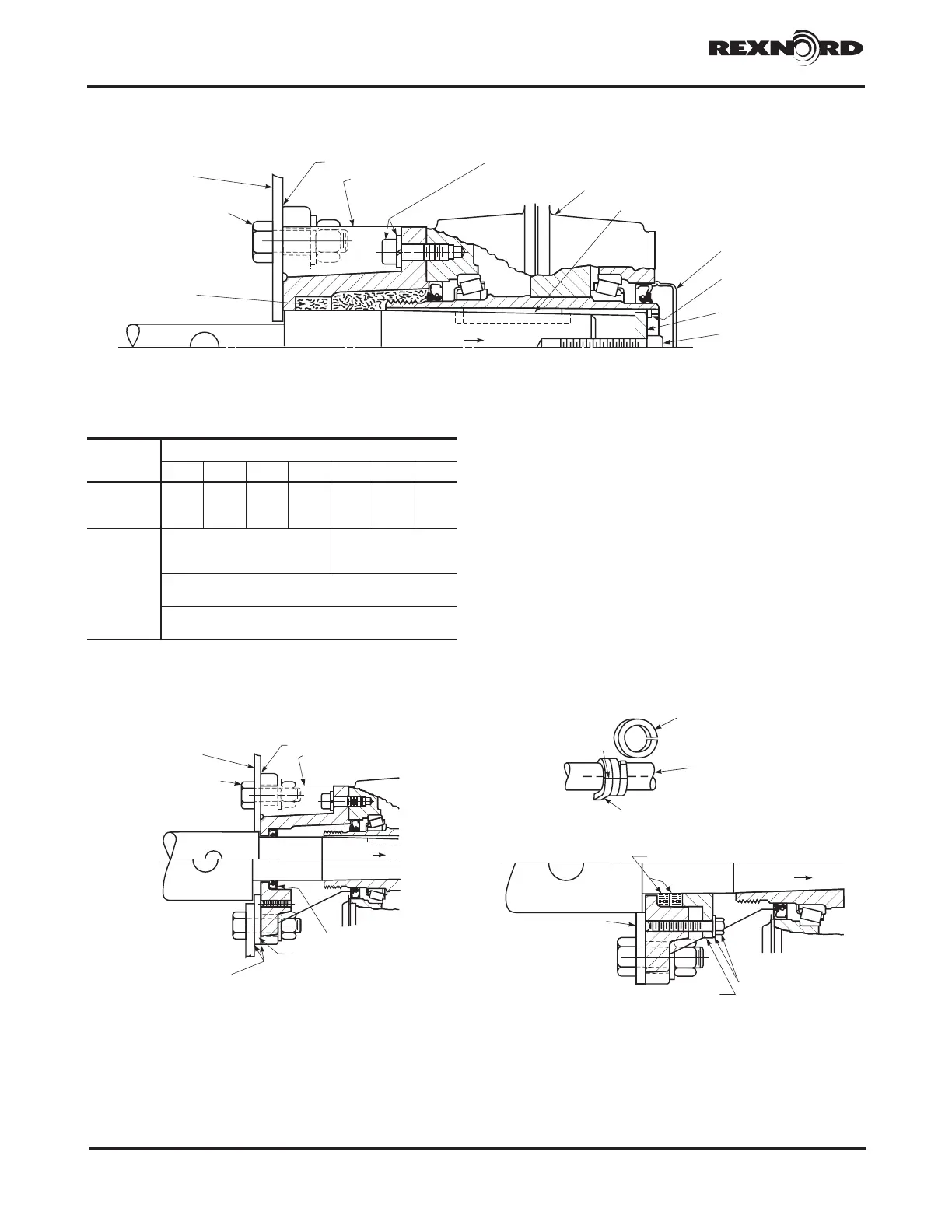
TROUGH END
TROUGH END
MOUNTING FASTENERS
DRIVE SHAFT
TROUGH END GASKET
SEAL HOUSING
INSERT
HOLLOW SHAFT COVER
SEAL HOUSING FASTENERS
WITH LOCK WASHERS
WASTE PACKING
BASIC DRIVE
DRIVE SHAFT KEY
THRUST PLATE
RETAINING RING
THRUST PLATE
DRIVE SHAFT THRUST
PLATE FASTENER
TABLE 4 — Seal Housing & Trough End
Fastener Size – UNC & Tightening
Torque (Non-Lubricated Fasteners)
Fastener
Location
DRIVE SIZE
5107 5115 5203 5207 5215 5307 5315
Seal Housing
Fasteners
lb-ft (Nm)
.500-13
69 (94)
.625-11
137 (186)
.750-10
245 (332)
.875-9
380 (515)
1.000-8
567 (769)
1.000-8
792 (1074)
1.000-8
792 (1074)
Trough End
Fasteners
lb-ft (Nm)
1.500” Diameter Drive Shaft
.500-13 Fasteners
69 (94)
2.000” & 2.437” Diameter Drive Shafts
.625-11 Fasteners with Nuts — 137 (186)
3.000” & 3.437” Diameter Drive Shafts
.750-10 Fasteners with Nuts — 245 (332)
Figure 7
b. LIP SEAL (Figure 8) — Coat outside diameter of
seal with Permatex #3 or equivalent. Drive seal into
seal housing with the spring-loaded seal lip away
from the driver. Wrap the keyway on tapered shank
of drive shaft with masking tape or lightweight Kraft
paper to protect against damaging the seal lips.
Coat the seal lips and straight portion of the drive
shaft with bearing grease. Line up the keyway in
the drive shaft with the hollow shaft keyway and
insert the drive shaft into the seal housing. Remove
the protective wrap and install the drive shaft key.
Insert the drive shaft into the hollow shaft. The seal
housing registers into the basic drive seal bore.
Use the thrust plate fastener, Figure 7, to secure the
drive shaft. Refer to Table 3 for proper torque value.
Install the seal housing fasteners to secure the
seal housing to the basic drive. Refer to Table 4 for
proper torque value. Reinstall hollow shaft cover and
proceed to Step 5.
SHAFT
BUTTJOINT
PACKINGGLANDROPE
CUT
PACKING GLAND RING
AFTER CUTTING
(TWO REQUIRED)
PACKING GLAND (TWO RINGS)
DRIVE SHAFT
TROUGH END
INSERT
COMPRESSION RING
COMPRESSION RING
FASTENER WITH
FLAT WASHER
Figure 8
Figure 9
Figure 10
c. PACKING GLAND SEAL (Figure 10) — First, wrap
the packing around the drive shaft adjacent to the
tapered portion of the drive shaft as shown in Figure
9. Cut the packing to produce two complete split
seal rings
CAUTION: Do not mar the shaft’s seal surface.
DRIVE SHAFT INSERT
TROUGH END
TROUGH END
MOUNTING FASTENERS
TROUGH END GASKETS
(SIZE 5107 WITH 2.437” &
3.000” DRIVE SHAFTS ONLY)
TROUGH END GASKET
SEAL HOUSING
MECHANICAL LIP SEAL
TROUGH END SPACER
(SIZE 5107 WITH 2.437” &
3.000” DRIVE SHAFTS ONLY)