Owners Manual • Falk Quadrive Shaft Mounted Drives Model A
(Page 8 of 52) Sizes 5107-5315
378-200 (PN-2128394) Rexnord
January 2019 3001 W. Canal St., Milwaukee, WI 53208-4200 USA
Supersedes 04-17 Telephone: 414-342-3131 Fax: 414-937-4359 www.rexnord.com
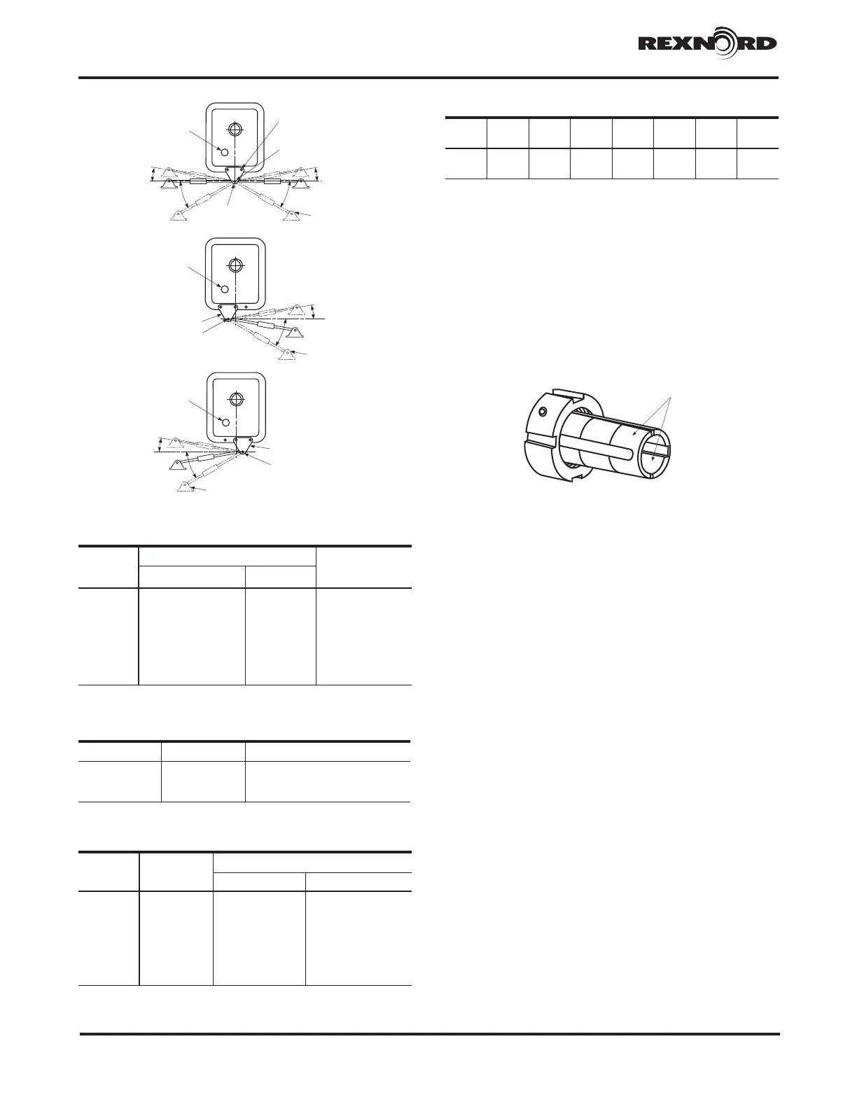
2°
30
°
HOUSING FLANGE
FASTENERS
2°
30° MAX
ANCHOR BRACKET
CLEVIS
BRACKET
5107 & 5115
HIGH-
SPEED
SHAFT
TORQUE ARM
FASTENER
MAX
2°
ANCHOR
BRACKET
HIGH-
SPEED
SHAFT
TORQUE ARM
FASTENER
5203 THRU 5315
CLEVIS
30° MAX
2°
3
0
°
MAX
HIGH
SPEED
SHAFT
ANCHOR
BRACKET
TORQUE ARM
FASTENER
CLEVIS
5203 THRU 5315
-
TABLE 6 — Spanner Wrench Type &
Spanner Nut Tightening Torque
DRIVE
SIZE
Adjustable Hook Spanner Wrench Spanner Nut
Tightening Torque
lb-ft (Nm)
GearWrench Williams
5107 81856 (2" to 4-3/4") 474 83 (113)
5115 81856 (2" to 4-3/4") 474 83 (113)
5203 81856 (2" to 4-3/4") 474 167 (226)
5207 81857 (4-1/2" to 6-1/4") 474A 167 (226)
5215 81857 (4-1/2" to 6-1/4") 474A 250 (339)
5307 81857 (4-1/2" to 6-1/4") 474A 250 (339)
5315 81858 (6-1/8" to 8-3/4") 474B 250 (339)
TABLE 7 — Torque Arm Clevis Bracket
Fastener Tightening Torque
DRIVE
SIZE
Fastener
Size
Tightening Torque – lb-ft (Nm)
Steel Foundation Concrete Foundation
5107 .375-16UNC 28 (38) 21 (28)
5115 .375-16UNC 28 (38) 21 (28)
5203 .500-13UNC 69 (94) 53 (72)
5207 .500-13UNC 69 (94) 53 (72)
5215 .625-11UNC 137 (186) 107 (145)
5307 .750-10UNC 245 (332) 191 (259)
5315 1.000-8UNC 567 (769) 467 (633)
c Grade 5 fasteners required.
Figure 12
TABLE 8 — Load Reaction Through Torque Arm
DRIVE
SIZE
5107 5115 5203 5207 5215 5307 5315
Load
lb (N)
2440
(10850)
3810
(16940)
4680
(20810)
6750
(27790)
9160
(40720)
12963
(57660)
15890
(70700)
c Load includes moment due to motor and motor mount with torque arm at
maximum angle.
10. JR — Thread the bushing nut onto the hollow shaft
one to two turns. NOTE: The bushing nut threads
have been coated with an anti-seize compound at
the Factory. This compound should not be removed.
Before re-installing a previously used nut, re-coat the
nut threads only with an anti-seize compound.
Note: In extremely severe or corrosive environments,
additional anti-seize compound MUST be applied to
the threads of the TA bushing nut.
WARNING: DO NOT apply anti-seize or lubricant to bushing or
shaft surfaces. Use of anti-seize may prevent secure connection
of the drive to the shaft and cause the drive to move.
WARNING: Overtightening can fail the internal retaining
ring (see Appendix G, for listing of retaining rings).
a. PREFERRED METHOD — Use a spanner (Table 6),
chain or pipe wrench to tighten the bushing nut to
the torque value indicated in Table 6. Apply Loctite
243 or equivalent to threads of setscrew. Tighten
the setscrew on the bushing nut to torque value
indicated in Table 6A.
b. ALTERNATE METHOD — (To be used when torque
cannot be measured.) Use a spanner (Table 6),
chain or pipe wrench to tighten the bushing nut
just until the drive can no longer be moved by hand
axially on the driven shaft. Loosen nut ONLY until it
can be turned by hand but do not unseat the taper.
Retighten the nut hand tight. Now mark a spot on
the top of the driven shaft. Next mark a spot on
the bushing nut 180° from the driven shaft mark
(90°CCW for sizes 5107 & 5115). Use the spanner
wrench to tighten the nut CW one half turn until the
two marks are aligned (one quarter turn for sizes
5107 & 5115). Apply Loctite 243 or equivalent to
threads of setscrew. Tighten the setscrew on the
bushing nut to torque value indicated in Table 6A.
11. JR — Install backstop, motor mount, motor, sheaves
(mount sheaves as close to the drive and motor housing
as possible), belts and guard. Refer to Appendix D for
motor mount installation instructions. Proceed to Step 14.
12. JF (USING TAPERED DRIVE SHAFT) — Put key into
the driven shaft. Lift drive into position and slide onto
the driven shaft taking care that the driven shaft key
seats into the hollow shaft keyway. DO NOT hammer
or use excessive force. Secure the drive to the shaft
with the thrust plate fastener. Refer to Table 3 for
torque value. Reinstall the hollow shaft cover. Install
motor mount, motor, sheaves, belts and guard. Refer
to Appendix D for motor mount installation instructions.
Proceed to Step 15.
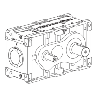
DO NOT apply ANTI-SEIZE
on these areas.
TABLE 6A — Bushing Nut Setscrew –
Tightening Torque
DRIVE SIZE Setscrew Size Tightening Torque lb-ft (Nm)
5107 .250-20 5 (7)
5115-5207 .312-18 11 (15)
5215-5315 .375-16 19 (26)