Easy Start Guide
Page 11
This guide has been produced by The Inverter Drive Supermarket Ltd.
All content, including but not limited to graphics, text and procedures copyright The Inverter
Drive Supermarket and must not be reproduced or altered without prior written permission.
©
Bosch Rexroth EFC 5610 Series Inverter
11. How to connect and configure a Run/Stop switch
with Forward/Reverse selection
The parameters described in Section 5 enable
Run/Stop operation via the red and green
buttons on the Inverter.
If this is unsuitable for the application, remote
switches can be used instead.
This section explains how to enable 2-wire
control with Run/Stop and Forward/Reverse
commands via separate selector switches.
Note that once this procedure is complete, the
Run/Stop buttons on the Inverter can no longer
be used.
11.1 Relevant parameters for remote Run/Stop
When stop is selected (X1 open circuit) the display
will decrease to zero as the motor decelerates.
Once at zero, the run lamp will go out. The display
will then revert to the speed reference.
If the application only requires the motor to turn in
one direction, the Forward/Reverse switch can be
omitted.
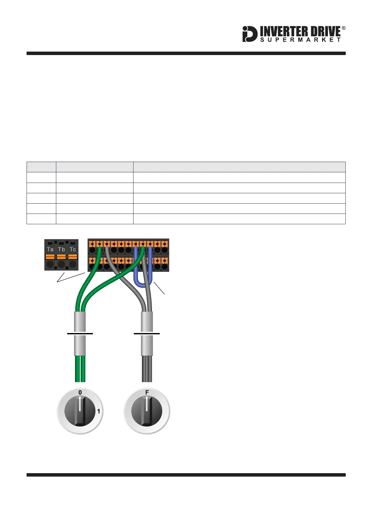
A wiring diagram is shown in the illustration
opposite. The SC and COM terminals must be
linked.
11.2 Connecting the Switches
When run is selected (24V to X1) and forward is
selected (X1 open circuit) the display will increase
from 0 to the speed reference as the motor
accelerates and the run lamp will illuminate.
Note: the Forward/Reverse switch only selects the
direction of rotation - it will not start or stop the
motor.
Two suitable 2 position NO (Normally Open)
switches should be installed: One between
terminals 24V and X1 (Run/Stop) and the other
between terminals 24V and X2
(Forward/Reverse).
13 12
R
Switch, 2 Position
Normally Open
“Forward / Reverse”
Switch, 2 Position
Normally Open
“Run / Stop”
EFC 5610
I/O Terminal
Blocks
24VSC COM
Link
cable
X2X1
3
21
Access to additional parameters
Default is 0 for Basic Parameters. Set to to enable Advanced Parameters.2
Default is 0 for keypad. Set to for terminal control on the Inverter1
Default is for Forward Run; default is required for this example.35
Default is for Reverse Run; default is required for this example.36
2-wire / 3-wire control mode
Default is 0. Set to for 2-wire forward / reverse, run / stop.1