2.2 Power Terminals
The table below describes the symbols on the frequency converter's power con-
nection terminals and their function.
Terminal Description
L1, L2, L3 Mains power supply inputs
U, V, W Frequency converter outputs (to be connected to the motor)
PB
Reserved terminal for external brake resistor (applicable to 0K75...15K0 frequency
converters)
P1, (+) DC positive bus outputs
(–) DC negative bus output
Grounding
Tab. 2-3: Power terminals description
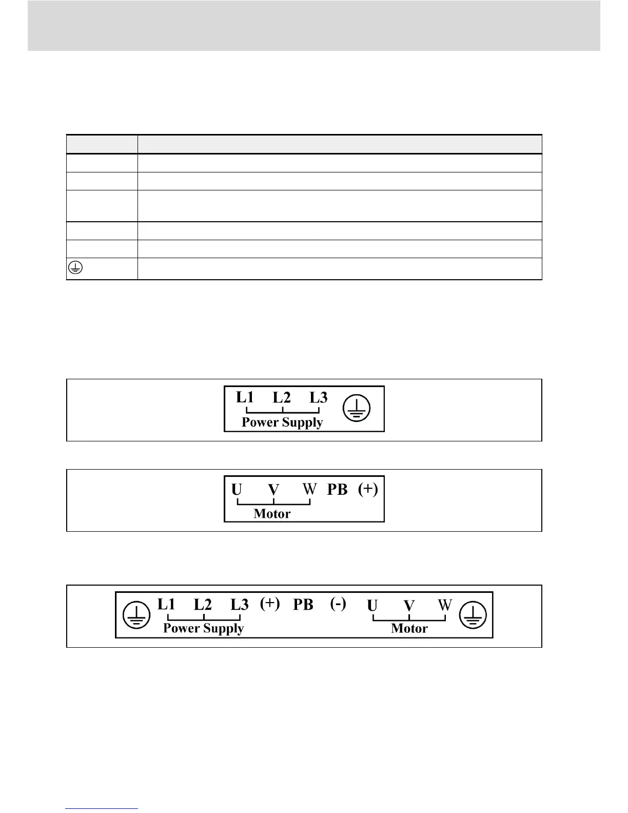
Depending on size, the position and sequence of the power terminals on the in-
dividual frequency converter may differ. Refer to the graphics below for the ex-
act connection terminal position and sequence.
Applicable to 0K75...7K50
Fig. 2-2: Power terminals_Frame 1_Top
Fig. 2-3: Power terminals_Frame 1_Bottom
Applicable to 11K0...15K0
Fig. 2-4: Power terminals_Frame 2
Bosch Rexroth AG
Electric Installation
10/31
DOK-RCON01-FE*********-IN04-EN-P
 Loading...