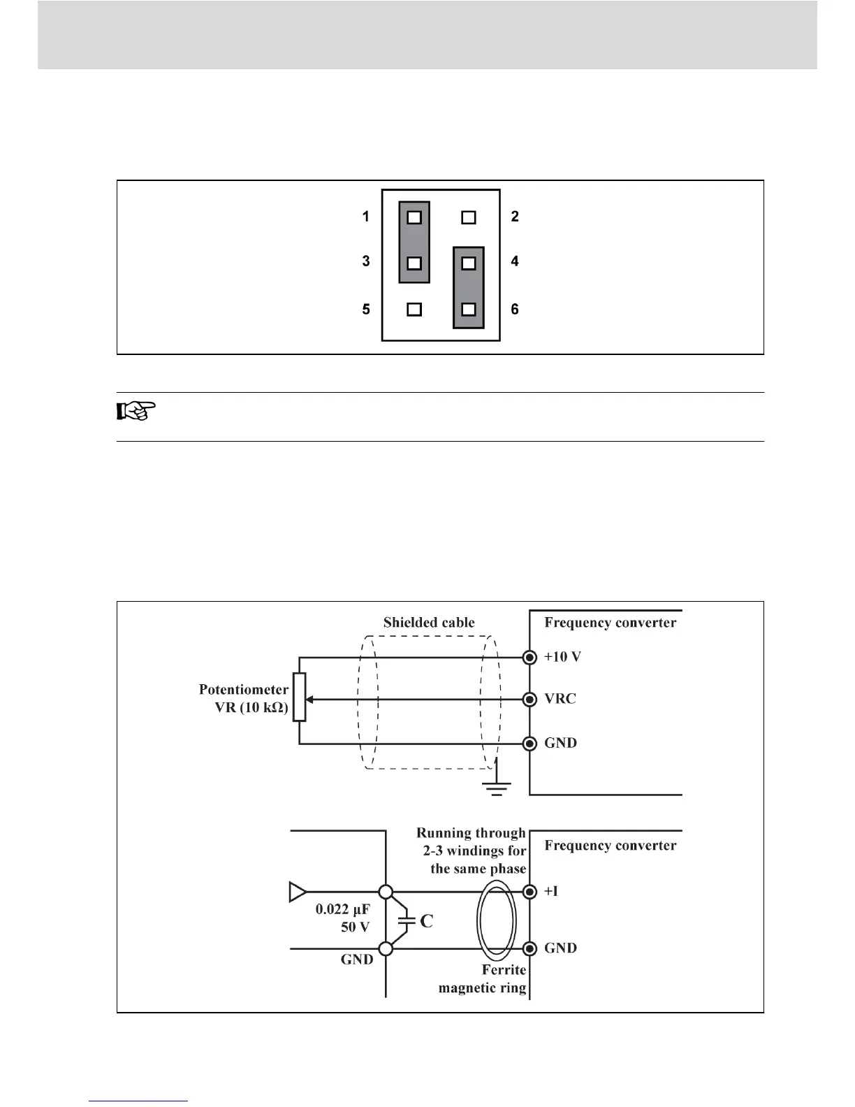
2.3.3 NPN/ PNP Mode Selection
Jumper SW
Fig. 2-11: NPN/PNP Jumper SW
As shown in the figure above, the factory default setting of the jump-
er is NPN.
Jumper SW determines:
1. The internal 24 V power supply or an external 24 V power supply.
2. The inputs are activated by connection of 24 V to an input (PNP/ active in-
put) or connection of 0 V to an input (NPN/ passive input).
2.3.4 Analog Input Terminal (+10 V, VRC, GND, +I)
Fig. 2-12: Analog input terminal
Bosch Rexroth AG
Electric Installation
DOK-RCON01-FE*********-IN04-EN-P
13/31
 Loading...