1. For connection of low level analog signals, which are easily af-
fected by external interference, the wiring length should be as
short as possible (less than 20 m), shielded cables must be
used.
2. Incorrect operation may occur due to interference on the ana-
log signal. In such cases, connect a capacitor and ferrite core at
the output side of the analog signal, as shown above.
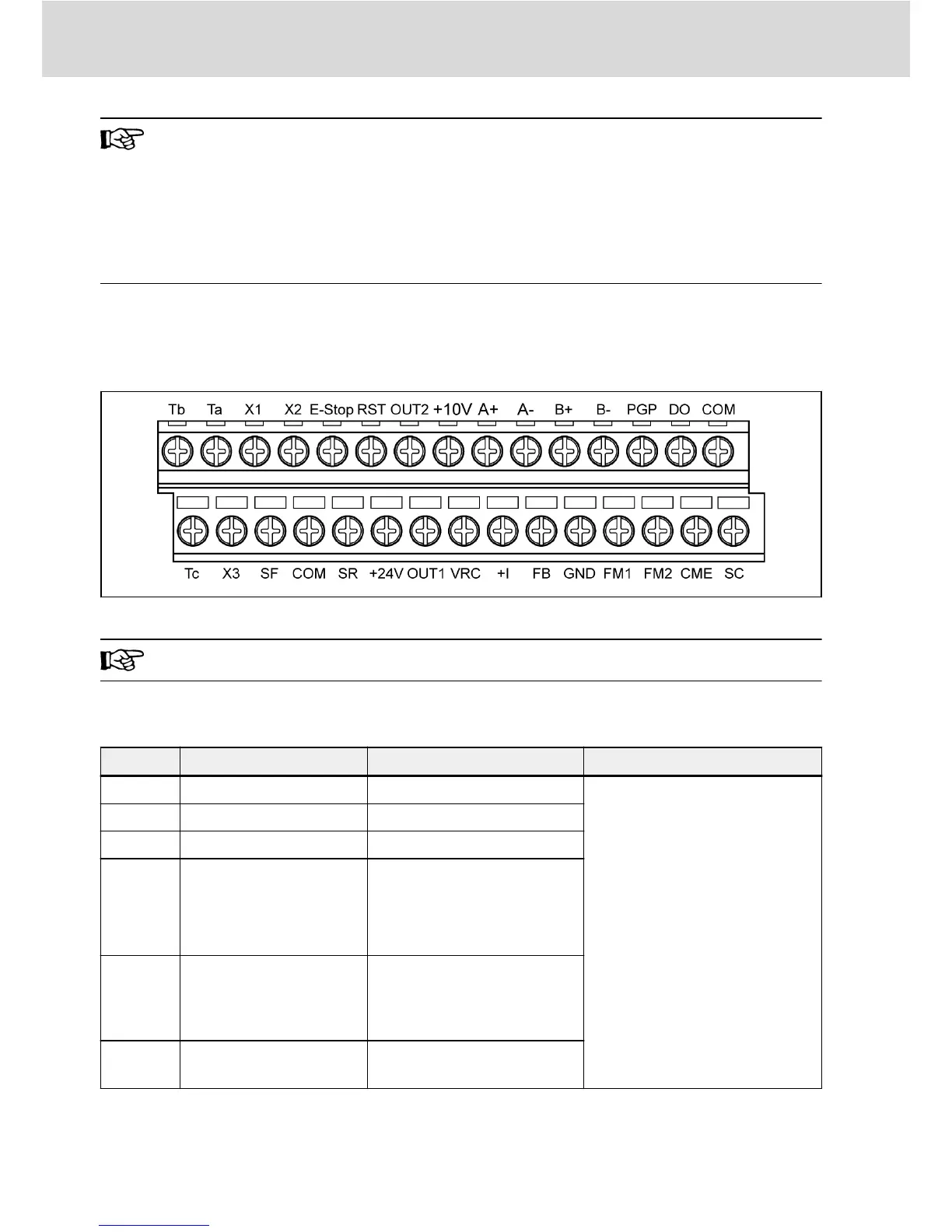
2.3.5 Control Circuit Terminals
Control circuit terminals figure
Fig. 2-13: Control circuit terminals
Applicable to 0K75...160K CPU board.
Control circuit terminals description
Terminal
Signal function Description Signal requirement
SF Forward/stop See parameters b00 and E38
Opto-electronic coupler isolated
input, 24 VDC for external power
supply
NPN/PNP modes, see fig. 2-11
"NPN/PNP Jumper SW" on page
13 for details
SR Reverse/stop See parameters b00 and E38
RST Error reset "Connected" for reset
E-Stop
External abnormality in-
put
[E32] = 0: "Connected",
coasting to stop
[E32] = 1, "Disconnected",
coasting to stop
X1
X2
X3
Multi-function inputs
See parameters b00, b34,
b35, b45, E39, H07 and H23
SC
Shared connection for
digital signals
Shared connection for SF\SR
\RST\E-Stop\X1...X3
Tab. 2-4: Digital inputs
Bosch Rexroth AG
Electric Installation
14/31
DOK-RCON01-FE*********-IN04-EN-P
 Loading...