Form CP-MAPS-D12 with FX05, P/N 209341 Rev 4, Page 1
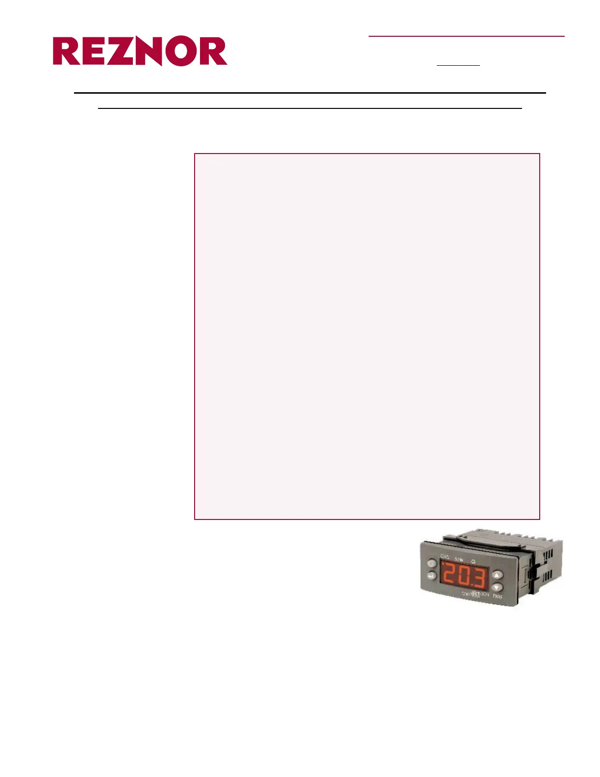
The microprocessor unit (Model FX05) in
control Option D12 is custom programmed
for the Reznor Modular Air Processing Sys-
tem (MAPS
®
II). Control features include:
• Custom 3-step control sequence of
cooling, dehumidication (reheat), and
heating
• 6:1 Gas heating modulation control option
• Fully integrated outdoor ambient lockouts based on outdoor dry
bulb/dewpoint or enthalpy
• Alarm and equipment shutdown features
• Service/Commissioning Test Mode
• Integrated timer functions for cooling and heating (optional)
There are four buttons that can be used for adjusting setpoints, viewing unit
status; and enabling unit test or shut down modes. (See FIGURE 2, page 3.)
The controller display will indicate unit status (on, off, or alarm), discharge air
Form CP-MAPS-D12 with FX05 (Version A)
Obsoletes Form CP-MAPS-D12
Application and Instructions for Field Adjustment of the Control (Model FX05)
in Digital Control Option D12, Space Control with Discharge Air Reset
Applies to Reznor MAPS
®
II Models RCA, RDA, RDCA, RDDA, RECA and REDA
(Includes worksheet to record adjustable parameters on pages 26 - 27.)
TABLE OF
CONTENTS
Introduction . . . . . . . . . . . . . . . . . . . . . . . . . . . . . . . . . . . . . . . . . . . .1
General Sequence of Operation . . . . . . . . . . . . . . . . . . . . . . . . . . .2
Display . . . . . . . . . . . . . . . . . . . . . . . . . . . . . . . . . . . . . . . . . . . . . . . .3
Installation Warnings and Notes . . . . . . . . . . . . . . . . . . . . . . . . . . .4
Unit Power and Blower Operation . . . . . . . . . . . . . . . . . . . . . . . . . .4
General Operation . . . . . . . . . . . . . . . . . . . . . . . . . . . . . . . . . . . . 4
Heating and Cooling Control Modes . . . . . . . . . . . . . . . . . . . . . . . .5
Heating Mode . . . . . . . . . . . . . . . . . . . . . . . . . . . . . . . . . . . . . . . 6
Cooling Mode. . . . . . . . . . . . . . . . . . . . . . . . . . . . . . . . . . . . . . . . 8
Dehumidication (Reheat) . . . . . . . . . . . . . . . . . . . . . . . . . . . . . . .12
Control Adjustment Guidelines for a Reheat System. . . . . . . . . 12
Unit Status Level . . . . . . . . . . . . . . . . . . . . . . . . . . . . . . . . . . . . . . .13
FX05 Commissioning Parameters Level . . . . . . . . . . . . . . . . . . .14
Time Clock (Option BHB1 required.) . . . . . . . . . . . . . . . . . 17
Alarm Displays . . . . . . . . . . . . . . . . . . . . . . . . . . . . . . . . . . . . . . . .17
Auto Test Mode . . . . . . . . . . . . . . . . . . . . . . . . . . . . . . . . . . . . . . .19
Sensor Data and Application . . . . . . . . . . . . . . . . . . . . . . . . . . . . .19
Optional Space (Wall-Mounted) Sensors. . . . . . . . . . . . . . . . . . 19
Discharge/Duct Sensor . . . . . . . . . . . . . . . . . . . . . . . . . . . . . . . 20
Outside Air Sensors . . . . . . . . . . . . . . . . . . . . . . . . . . . . . . . . . . 22
Wall-Mounted Sensor and Communication Wire Installation. . . 22
Physical Point List . . . . . . . . . . . . . . . . . . . . . . . . . . . . . . . . . . . . .23
BAS Card Options. . . . . . . . . . . . . . . . . . . . . . . . . . . . . . . . . . . . . .24
Lon Card, Option BHB3 . . . . . . . . . . . . . . . . . . . . . . . . . . . . . . . 24
N2 Open Card, Option BHB2. . . . . . . . . . . . . . . . . . . . . . . . . . . 24
Network Points List. . . . . . . . . . . . . . . . . . . . . . . . . . . . . . . . . . . . .25
WORKSHEET for Adjustable Parameters
(See pages 14-17 for explanations.) . . . . . . . . . . . . . . . . . . .26
Index. . . . . . . . . . . . . . . . . . . . . . . . . . . . . . . . . . . . . . . . . . . . . . . . .27
Introduction
Applies to: MAPS
II Controls
FX05