Form CP-MAPS-D12 with FX05, Page 22
Outside Air Dry Bulb Sensor and Dewpoint or Enthalpy
Permissive Control
The outside air sensor (P/N 206112) for the FX05 is the same as the dis-
charge sensor. The Johnson A99 Series Temperature Sensor Chart on page
21 applies to both the discharge and outside air sensors.
If the application uses mixed air (return and outside air), the outside air tem-
perature sensor and optional humidity transmitter (FIGURE 10B) must be
mounted together to sense outdoor air conditions. Verify that factory mounted
positions provide acceptable performance.
Sensor Accuracy and Outside Air Changeover Differential
Dry bulb sensor accuracy is within 1°F between 5° and 167°F. Outside air
dewpoint is calculated based on a humidity transmitter (FIGURE 10B) input.
Accuracy is rated as follows:
Humidity transmitter ± 3% RH for 20 to 80% RH at 77°F and ±5% RH for 10
to 20% and 80 to 90% RH at 77°F. The dewpoint calculation is within 1%
error at sea level. Hysteresis and the rate of moisture change also have an
impact on sensor accuracy. Prolonged periods of high humidity (above 95%
RH) can affect sensor accuracy (the bias is towards a higher RH reading than
actual). The calculated outdoor dewpoint should be veried on an annual basis
to ensure proper changeover operation.
FIGURE 10B - Outside
Air Relative Humidity
Transmitter, Option
DT5, P/N 206081
Outside Air Sensors
Control Wiring
IMPORTANT: The FX05 control wiring control inputs are low-current, resis-
tance-based signals. The control manufacturer recommends for optimum tem-
perature control performance that the analog and digital inputs (space sensor,
discharge air sensors, etc.) that are connected to the FX05 controller be routed
to the unit in one of the following manners:
• In separate conduits, isolated from 24VAC controls and line voltage power to
the unit.
OR
• If the FX05 wires are to be run in the same conduit as the 24VAC control
wiring, the FX05 wiring must be completed using shielded cable and bundled
separately from 24VAC control wiring. The shield must be drained at the unit
and taped on the opposite end.
Wall-Mounted
Sensor and
Communication
Wire Installation
Before connecting or disconnecting any wires, ensure that all power supplies
have been switched off and all wires are potential-free to prevent equipment
damage and avoid electric shock.
Sensor Data and Application (cont’d)
Wiring terminations in space sensor, Option CL53 (FIGURE 7, page 19), are
made at the terminal blocks in the base of the module. Those terminal blocks
will accept up to 1.5 mm
2
(AWG 16) wires. To access the terminals, remove the
cover from the base of the module by inserting a pointed tool into the small hole
at the center top of the cover. While pressing down gently, pry the cover away
from the base. As the two parts separate, remove the tool and continue to pull
the cover away from the base until the cover is free.
All wiring to the module is at extra low (safe) voltage and must be separated
from line voltage wiring. Do not run wiring close to transformers or high fre-
quency generating equipment such as a lighting ballast. Complete and verify
all wiring connections before applying power to the controller connected to the
module. Under the lateral cover on the space sensor, service connector pins
provide for serial connection if the optional serial card (N2Open or LON) is
inserted in the FX05 controller and properly connected to the room command
module pins 10, 11, and 12.
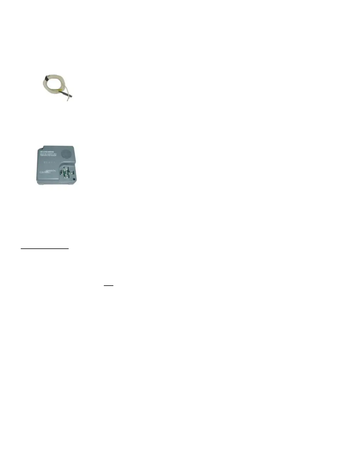
FIGURE 10A - Outside
Air Dry Bulb Sensor,
P/N 206112