Form CP-MAPS-D12 with FX05, Page 24
1
2
3
FIGURE 11 - LON
Card for FX05
Control, Option
BHB3
P/N for Option BHB3
with software for
Gas Control Option
AG55 is 220747;
P/N for Option BHB3
with software for
Gas Control Option
AG57 is 209877
BAS Card Options
Pin Twisted pair
1 NET A
2 NET B
3 COM
Lon Card, Option BHB3
The LON Serial Card is a plug-in card that allows the FX05 control to be con-
nected to a LON network. The connection to the network is made by means
of the 3 pins on the plug-in connector. The meaning of each pin is shown in
FIGURE 11.
The network cable must be laid along a low voltage cable path. It must be
placed at least 12” (30 cm) from cables carrying high voltages or currents
(>230V or >30A). If strong interference elds are expected, the cable must be
located at the greatest distance possible from the source. The TP/FT-10 net-
work is designed to support free topology wiring, and will accommodate bus,
star, loop or any combination of these topologies. FTT-10A transceivers can be
located at any point along the network wiring.
LON network: Doubly-Terminated Bus Topology; Free topology (single termi-
nator required).
Nodes: 64 (if repeaters are not used), FTT-10 nodes only.
Cable Type
Length with FFT-10 devices
Bus topology Free topology
Belden 85102 8858 ft (2700m) 1640 ft (500m)
Belden 8471 8858 ft (2700m) 1640 ft (500m)
Level IV 22 AWG 4593 ft (1400m) 1312 ft (400m)
Power link topology supported.
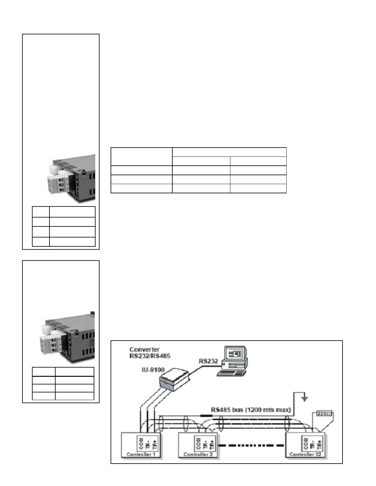
N2 Open Card, Option BHB2
The N2Open serial card is a plug-in, optional card that allows the controllers of
the FX05 line to be connected in a N2Open serial network through the RS485
standard. The connection to the network is made by means of the 3 pins on the
plug-in connector shown in FIGURE 12.
The network cable must be laid along a low voltage cable path. It must be
placed at least at 12” (30 cm) from cables carrying high voltages or currents
(>230V or >30A). If strong interference elds are expected, the cable must be
located at the greatest distance possible from the source. The communication
line must be laid out on the multi-drop line principle, i.e. from one controller to
the next until the last controller has been connected. The line must be termi-
nated at both ends with a 220 Ohm resistor between RT+ and RT-.
RS485 line: maximum length without repeater: 3937 ft (1200 M), AWG26
twisted pair with shield.
RS232C line: maximum length: 33 ft (10 m)
Devices: maximum of 32 per 3937 ft (1200 m) bus segment
Pin RS485
1 COM
2 RT-
3 RT+
1
2
3
FIGURE 12 -
N2Open Card for
FX05 Control,
Option BHB2,
P/N 206077