Form CP-MAPS-D12 with FX05, P/N 209341 Rev 4, Page 19
Auto Test Mode
Press both the enter and down arrow key for three seconds (press the enter
key an instant prior to pressing the down arrow key). Controller ashes “tst”
and the blower is enabled. No other action needs to be taken. The unit will
cycle all outputs and automatically skip to the next mode in one-minute inter-
vals. The outputs are sequenced as follows:
1.
Fan/Blower (always enabled)
2. 1st stage heat (H1)
3. 2nd stage heat (H2)
4. Reheat output (rH) (Reheat output applies to Models RDA, RDDA,
REDA with standard reheat and Models RCA, RDCA, or RECA
with Option AU25 Supplemental Reheat Coil)
5. 1st stage cooling (C1)
6. 2nd stage cooling (C2)
Upon completion, unit will exit test mode and return to the auto mode state. If
preferred, the user can override the auto test mode by pressing the up arrow
key for approximately three seconds (hold the up arrow key down until the unit
shifts to the next mode) to jump from mode to mode. (NOTE: While holding the
key down button, the display will temporarily show sensor values.)
In this test sequence, the output is energized for 15 minutes or until the up
arrow key is pressed. If desired, pressing the up arrow key for approximately
one second will extend the current test mode by 15 minutes (total of 30 min-
utes). The user may exit test mode at any time by pressing the down arrow key
for 3 seconds.
Sensor Data and Application
Optional Space
(Wall-Mounted)
Sensors
Space Temperature Sensor - The wall mounted sensor should be located on
an interior wall (avoid direct placement in the sun), the wall opening should be
insulated to prevent cold drafts and the sensor located for sampling represen-
tative space air.
Room RH Input with Reheat Mode - Since reheat is already
enabled based on outdoor dewpoint, a room RH control is
typically not required for rooftops that condition 100% out-
side air. A wall mounted RH control (FIGURE 8) is typically
specied when internal latent loads vary considerably, the
rooftop is applied with return air, or an unoccupied space RH
control is desired. When applied with an RH input, reheat is
enabled if space RH is above setpoint and the space cooling load is satised.
During unoccupied mode, a rise in room RH will enable the dehumidication
and reheat circuit. If there is no call for space cooling, only the reheat pump is
enabled (cooling compressors are locked out).
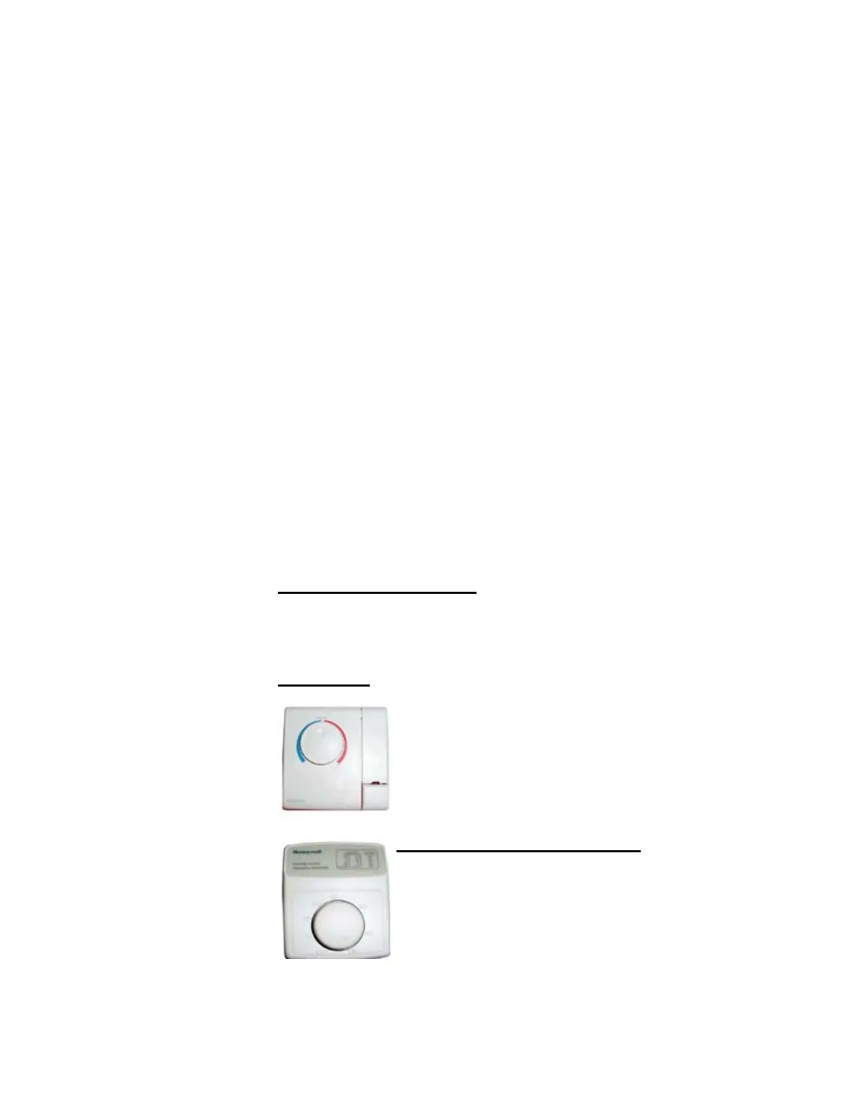
FIGURE 8 -
Wall-Mounted
Dehumidistat,
Option CL47,
P/N 177231
FIGURE 7 - Optional
Wall-Mount Space Air
Sensor, Option CL53,
P/N 207239
Option CL53 is a wall-mount space sensor control that provides:
Space temperature sensing
Occupied (boost) and unoccupied override button
LED fan alarm status (except on heat systems with
gas modulation).
NOTE: Setpoint dial on CL53 control is inactive with
Option D12