Form CP-MAPS-D12 with FX05, P/N 209341 Rev 4, Page 21
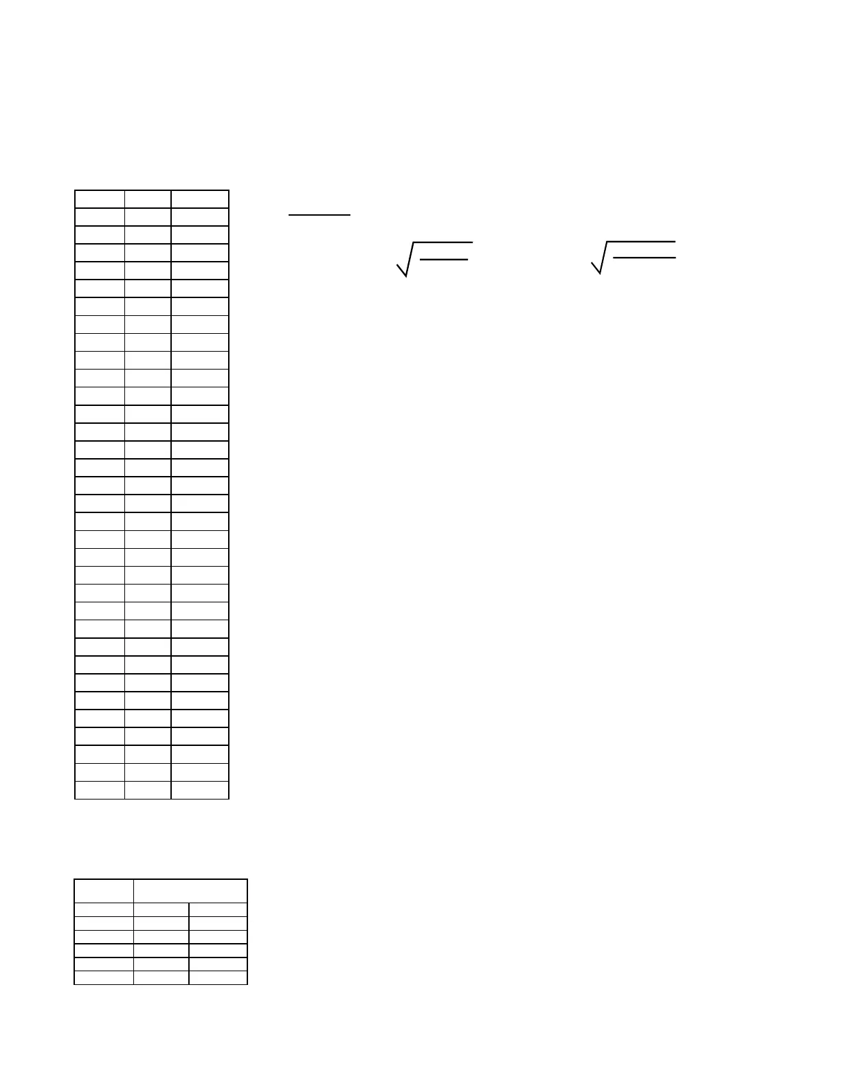
Sensor Data for
Johnson A99 Series
Temperature Sensors
- Resistance vs
Temperature (applies
to both discharge and
outside air sensor)
°F °C Ohms
-40 -40 613
-31 -35 640
-22 -30 668
-13 -25 697
-4 -20 727
5 -15 758
14 -10 789
23 -5 822
32 -0 855
41 5 889
50 10 924
59 15 960
68 20 997
77 25 1035
86 30 1074
59 35 1113
104 40 1153
113 45 1195
122 50 1237
131 50 1279
140 60 1323
149 65 1368
158 70 1413
167 75 1459
176 80 1506
185 85 1554
194 90 1602
203 95 1652
212 100 1702
221 105 1753
230 110 1804
239 115 1856
248 120 1908
1. Determine the appropriate distance from the unit. Be sure there is
sufcient distance from the outlet to have a good mixture of discharge air
temperature. According to the latest edition of AMCA Standard 201, in
straight ducts, the air is typically well mixed a minimum of ve equivalent
duct diameters from the discharge of the unit with equivalent duct diameter
dened as equal to the square root of 4AB/3.14. “A” and “B” are the duct
cross-sectional dimensions.
Example: Supply ductwork cross-sectional dimension is 24” x 12”
(610mm x 305mm).
5 x
= 96” 5 x
= 2435mm
Locate the sensor a minimum of 96” (2435mm) from the
outlet of the unit.
Important NOTES: If the length of the discharge duct is less than 12 ft
(3.7M), a mixing vane is recommended for mixing the discharge air.
Do not mount the sensor in the ductwork after a split in the supply as that
will cause loss of control in the duct that does not house the sensor.
2. Determine the location and orientation of the sensor holder assembly.
The position of the sensor holder in the duct is also important. In horizontal
ductwork, locate the sensor assembly in the top, middle of the duct with the
sensor holder extending vertically down into the center of the airstream. In
vertical ductwork, locate the sensor assembly in the middle of the side of
the duct that corresponds with the top middle of the discharge outlet. The
sensor holder will extend horizontally into the center of the airstream.
Push the sensing element into the clip attached to the inside of the sen-
sor holder. Turn the metal holder so that the element will be shielded from
direct airow and will sense the temperature in the airstream as it ows
through the holes in the sensor holder.
At the location selected, mark the diamond-shaped hole required for the
sensor holder. Cut the hole no larger than required for the holder, approxi-
mately 1” x 1” (25mm x 25mm).
In the electrical box portion of the sensor holder, determine where the sen-
sor wire should come through the box and remove the knockout at that
location.
3. Attach the sensor holder assembly.
Slide the sensor holder into the
opening in the ductwork. Using four eld-provided No. 6 sheetmetal
screws, attach the box to the ductwork. Attach a eld-supplied cable con-
nector to the box, run the sensor wire out, and attach the cover to the box.
4.
Run the sensor wire to the unit. Digital control inputs are low-current,
resistance-based signals. The manufacturer recommends for optimum
temperature control performance that the analog and digital inputs (zone
sensors, discharge air sensors, etc.) that are connected to the FX05 con-
troller be routed to the unit in one of the following manners:
• In separate eld-supplied conduits, isolated from 24VAC controls and
line voltage power to the unit,
OR
• If the FX05 wires are to be run in the same eld-supplied conduit as
the 24 VAC control wiring, the FX05 wiring must be completed using
shielded cable and bundled separately from 24 VAC control wiring. The
shield must be drained at the unit and taped on the opposite end.
NOTE: Wire supplied with
the sensor is 22 AWG.
Maximum Sensor
Wire Length for
less than 1°F Error
Wire
Gauge
Maximum Sensor Wire
Length
AWG Feet Meters
14 800 244
16 500 152
18 310 94
20 200 61
22 124 38
Instructions for Installing Sensor in Discharge Duct