Form I-MAPSIII&IV, Page 12
Installation Instructions
for Down Discharge
Roof Curb, Option
CJ31, for MAPS
®
Cabinet Sizes A, B, and
C
NOTE: For A, B, or C with
energy recovery Option
ER1, see page 14.
CAUTION: Before installation, recheck to be sure that the correct curb
has been ordered. Be sure that the curb selected matches the unit
ordered. Verify the dimensions of the curb received with the appropriate
dimension table.
1. Position the roof curb ends (Code A) and sides (Code B) as shown in the drawing
in FIGURE 7A. Fasten with bolts and lag screws as illustrated in the corner detail
(FIGURE 7B).
2. Install bottom opening ductwork. Use the sheetmetal screws to attach the dividers
(Codes C1, C2, D1, D2, E, & F in FIGURE 7A). Attach the return air duct angles
(Codes G & H) to the attached end and side and to the roof curb. NOTE: If the
system does not have a return air opening, Codes F, G, & H may be installed in
the curb but are not required.
3. Check the roof curb for squareness. The curb must be adjusted so that the
diagonal measurements are equal within a tolerance of ±1/8” (±3mm).
4. Level the roof curb. To ensure a good weatherproof seal between the unit curb cap
and the roof curb, the roof curb must be leveled in both directions with no twist end
to end. Shim as required and secure curb to the roof deck before installing ashing
(See Curb Detail in FIGURE 7B).
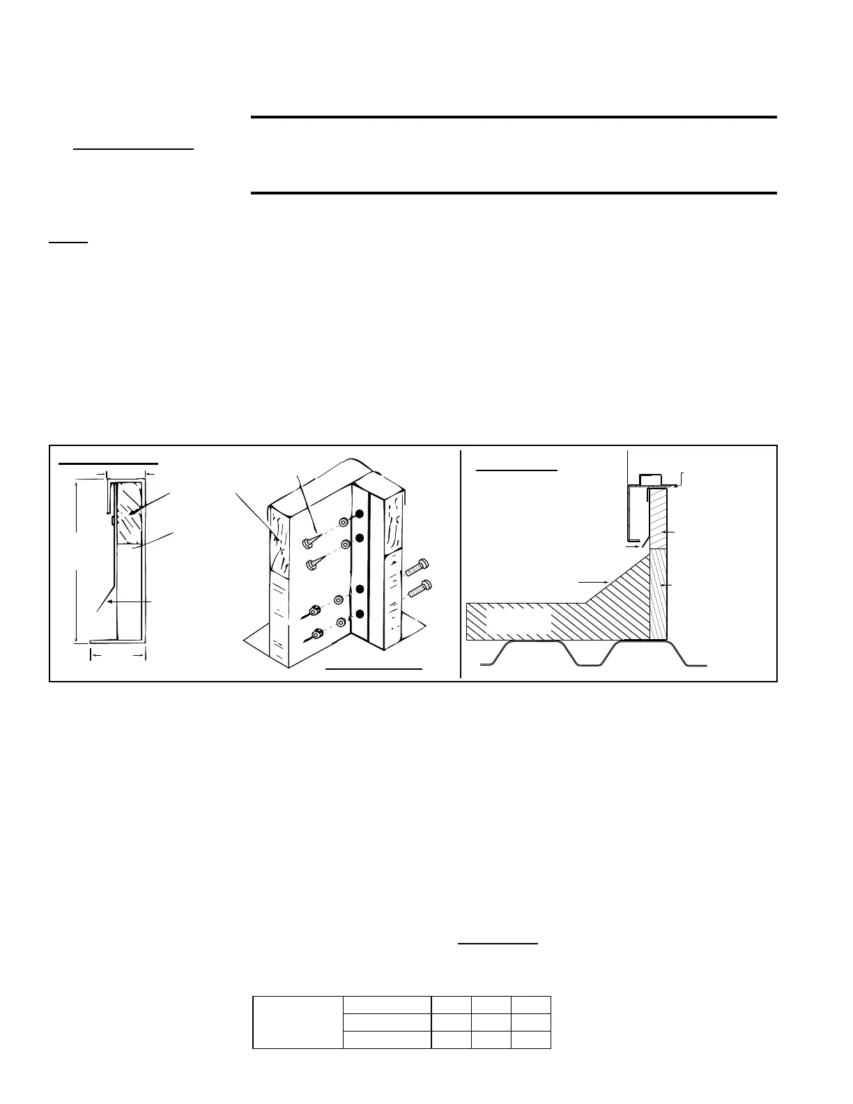
FIGURE 7B - Option
CJ31 Downow Roof
Curb Cross Section and
Corner Detail
MUST be sealed
between curb cap
and top of curb
Cabinet
2x4 Wood Nailer
Counter Flashing
(by installer)
Cant Strip
(by installer)
Weld, bolt, or lag screw curb to deck structure.
Roofing Felts
(by others)
Insulation
Curb Detail
Corner Detail
Curb Section
5. Install eld-supplied ashing.
6. Before placing the MAPS
®
unit or optional duct furnace (Option JH25 or JH30) on the curb:
□If ductwork is being installed from the top, slide the ductwork down into the
discharge and return air openings. Ductwork should be sized slightly smaller with
a minimum 3/4" duct ange that will rest on and be attached to all sides of the duct
connection. See duct connection requirements in Paragraph 6.4.
□Apply 1/4" x 1-1/4" foam sealant tape to both the top surface of the curb rails
and the top surface of the perimeter of the integral dividers, being sure to make
good butt joints at all corners. The sealant tape must be applied to prevent water
leakage into the curb area due to blown rain and capillary action.
□If installing an optional duct furnace curb section (Option JH), place it on the roof
curb before the unit. See Paragraph 5.4.3.
□When it is time to lift the MAPS
®
unit or optional duct furnace onto the prepared
curb (See Rigging and Lifting in Paragraph 5.5.), be sure that all of the above
preparations have been made. IMPORTANT: Verify that the unit will be placed in
the correct airow orientation to mate properly with the discharge and return air
openings.
5.4 Mounting on a Roof Curb (cont'd)
5.0 Mounting
(cont'd)
5.4.1 Downow Roof Curbs for MAPS
®
Cabinets A, B, C (cont'd)
5.4.1.1 Curb for Vertical (Down) Airow (Option CJ31) (cont'd)
Weights by Cabinet
Size* - Downow Roof
Curb Option CJ31
* See chart on pages 71-72 for cross-
reference by Model Size or Model
and Heat Size to Cabinet Size.
Option CJ31
Roof Curb
Weight
Cabinet Size * A B C
lbs 93 105 235
kg 42 48 107

 Loading...
