Form I-MAPSIII&IV, Page 64
Electric Heat Capacity and Sequence of Operation - Cabinet Sizes A, B, C
NOTE: 575V & 600V apply to RECB & RECC only.
Electric Heat Capacity Table
Size
240/480/600V 208V 230/460/575V
KW MBH KW MBH KW MBH
10S 10 34.1 7.5 25.6 9.2 31.4
15S 15 51.2 11.3 38.4 13.8 47.1
20S 20 68.3 15.0 51.2 18.4 62.8
24S 24 82.0 18.0 61.5 22.1 75.4
15 15 51.2 11.3 38.4 13.8 47.1
20 20 68.3 15.0 51.2 18.4 62.8
25 25 85.4 18.8 64.0 23.0 78.5
30 30 102.5 22.5 76.8 27.6 94.3
35 35 119.5 26.3 89.6 32.2 110.0
39 39 133.2 29.3 99.9 35.9 122.5
60 60 204.9 45.0 153.7 55.2 188.5
75 75 256.1 56.3 192.1 69.0 235.6
88 88 300.5 66.0 225.4 81.0 276.5
Size
(kW)
Size Cabinet
Electric Heaters Sequence of Operation
Stage
1
Stage
2
Stage 3 Stage 4
10 10S A 10 - - -
15 15S A 15 - - -
20 20S A 20 - - -
24 24S A 24 - - -
15 15 A or B 5 10 5 + 10 -
20 20 A or B 5 15 5 + 15 -
25 25 A or B 10 15 10 + 15 -
30 30 A or B 10 20 10 + 20 -
35 35 A or B 15 20 15 + 20 -
39 39 A, B, or C 15 24 15 + 24 -
50 50 B or C 10 10+10 10+10+15 10+10+15+15
60 60 B or C 10 10+10 10+10+20 10+10+20+20
75 75 B or C 15 15+20 15+20+20 15+20+20+20
88 88 B or C 20 20+20 20+20+24 20+20+24+24
9.0 Optional Equipment (cont'd)
9.3 lectric Heat - Models RECB, REDB, RECC, REDC (cont'd)
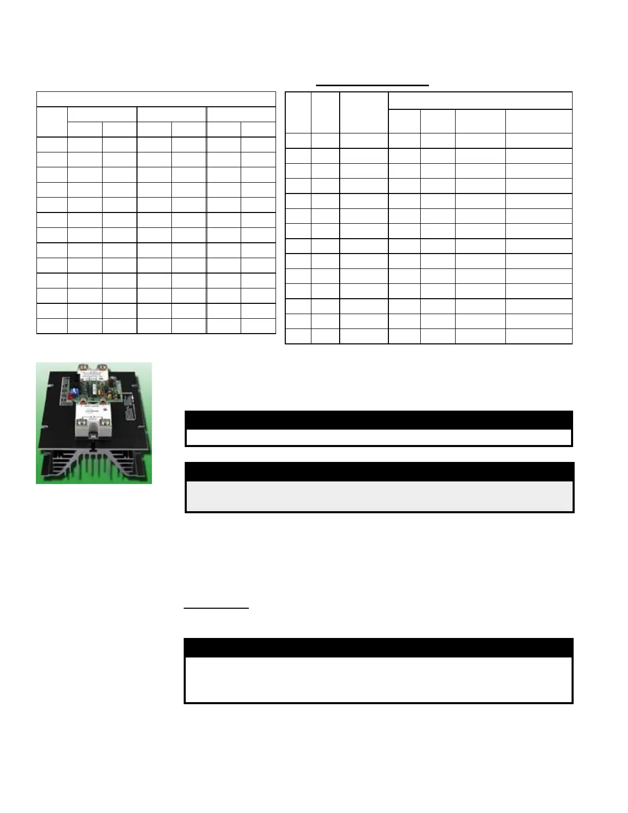
Modulating heating operation is controlled by an SCR modulating control. There will be
one or two SCR controllers located on an electrical panel in the electric heat section.
WARNING
The heatsink on the SCR power controller is hot to the touch.
FIGURE 47 - SCR
Controller for Electric
Heat Modulation
DANGER
High voltages are present on the terminals of the SCR power
controller(s).
9.3.2 Modulating Electric Heat
10.2 Checklist Prior
to Startup
Assumptions: All connections are made; actual startup is imminent. Site is clean; all
excess supplies, scraps, and debris have been removed. Clean lters are in place.
Doors are open for checks.
WARNING
To prevent injury or death due to electrocution or contact with
moving parts, lock disconnect switch open when doing checks
prior to startup.
NOTE: Redo cooling
startup procedures
when the cooling
season begins.
10.2.1 All Systems Checklist Prior to Startup:
Check clearances. All clearances must be as illustrated in Paragraph 4.1.
Verify the electrical supply matches voltage rating of the unit. (Refer to the rating
plate.)
10.1 General
Follow the procedures listed in Paragraphs 10.2 - 10.4 and ll in the Startup Form in
the APPENDIX, page 70.
10.0 Commissioning and Startup

 Loading...
