Form I-MAPSIII&IV, P/N 222917R9, Page 43
Before initial startup, connect refrigerant pressure gauges to the compressor suc-
tion and discharge lines. At startup, observe the gauges. If the suction pressure
rises and discharge pressure drops, the compressor is operating in reverse and
should be shut down. (After several minutes of operation in reverse, the compres-
sor’s internal protector will trip. If compressors are repeatedly allowed to restart and
run in reverse, the compressors will be permanently damaged.) Turn off the power. At
the incoming power connection, switch the 3-phase line voltage wiring connec-
tions before restarting the unit. Recheck the pressure gauges.
CAUTION: Connect pressure gauges to the suction and discharge
lines before startup so that compressor rotation can be checked
immediately. Scroll compressors will be destroyed if operated in
the wrong direction.
7.3 Wiring Diagram,
Unit Wiring
Requirements,
and Optional
Convenience
Outlet
Each unit has a custom wiring diagram in the control compartment. All optional elec-
trical components ordered with the unit are shown on the wiring diagram. Codes for
options ordered are listed across the bottom of the diagram. To identify option codes,
see list in APPENDIX, page 73.
Keep the wiring diagram and all manuals for future reference
CAUTION: If any of the original wire as supplied with the appliance
must be replaced, it must be replaced with wiring material having
a temperature rating of at least 105°C.
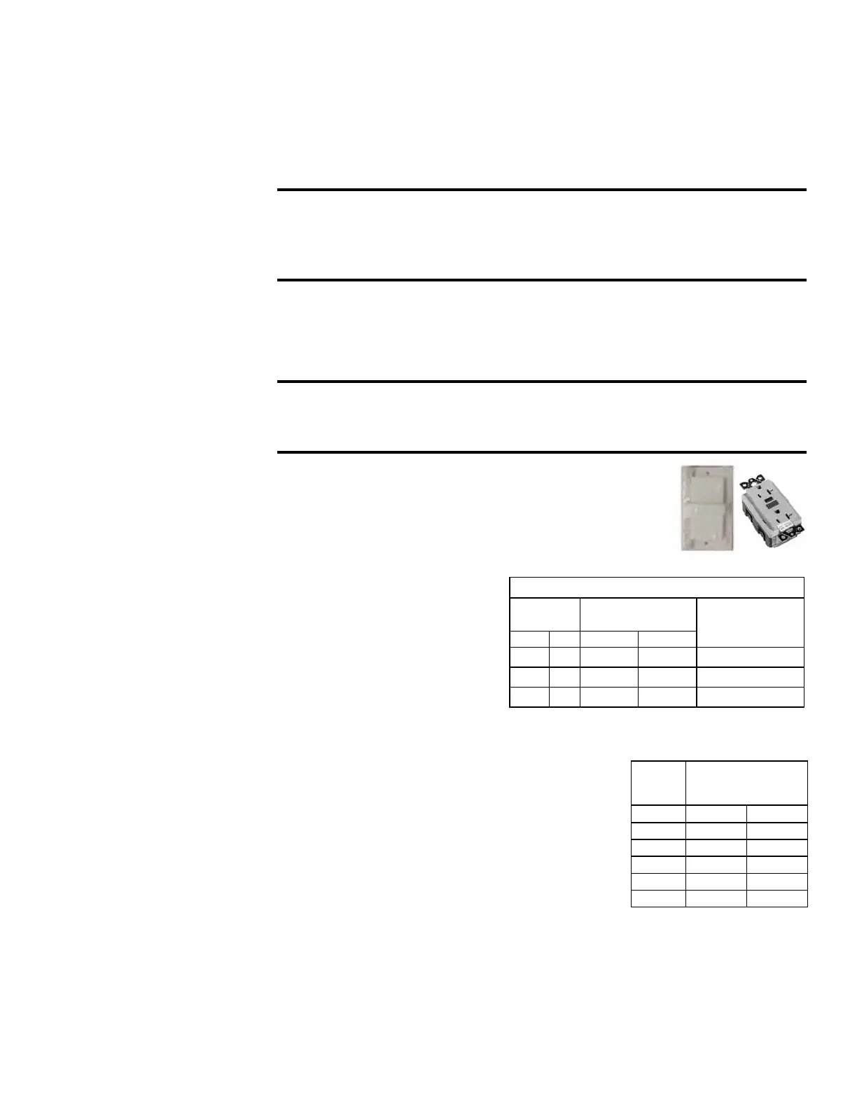
Optional Convenience Outlet, Option BC2
- If the
system was ordered with this option, it will have an external
weatherproof, factory-installed 115V outlet with ground fault
protection. This outlet requires a separate 115 volt power
supply.
7.4 Control Wiring
The unit is equipped with a low
voltage (24V) control circuit. 24V
wires enter the cabinet near the
line voltage entrance and must
be routed over to the low voltage
compartment. Connections are
made at the low voltage terminal
blocks.
Field Control Wiring Length/Gauge
Total Wire
Length
Distance from Unit
to Control
Minimum
Recommended
Wire Gauge
ft M ft M
150 46 75 23 18
250 76 125 38 16
350 107 175 53 14
Refer to the wiring diagram for wiring connections. Refer to the chart for control wire
gauge and length requirements.
Digital Control Wiring
Digital control inputs are low-current, resistance-based
signals. The manufacturer recommends for optimum
temperature control performance that the analog and
digital inputs (zone sensors, discharge air sensors, etc.)
that are connected to the controller be routed in one of
the following manners:
• In separate conduits, isolated from 24VAC controls
and line voltage power to the unit,
OR
Wire
Gauge
Maximum Sensor
Wire Length (Digital
Control)
AWG Feet Meters
14 800 244
16 500 152
18 310 94
20 200 61
22 124 38
• If the wires are to be run in the same conduit as the 24 VAC control wiring, the
digital control wiring must use shielded cable and be bundled separately from
24 VAC control wiring. The shield must be drained at the unit and taped on the
opposite end.
Refer to the wiring diagram for making wiring connections.
7.5 Blower Motor
Check the unit rating plate or motor name plate to verify voltage, HP, and type. Use
an amp meter to check motor amps. Amps may be adjusted downward by reducing
blower RPM or increasing duct system static pressure.

 Loading...
