Form I-MAPSIII&IV, P/N 222917R9, Page 51
Option VFC5, Building CO
2
Sensor
The sensor (P/N 234820) used in Option VFC5 must be eld mounted in the building
and electrically connected to the I/Q controller expansion board (Option BHB6). Follow
the manufacturer's instructions to mount the sensor. Connect the wires as instructed
below. Power supply must be connected to
and
FIGURE 29C - CO2
Sensor, P/N 234820
CAUTION: The same
ground reference
has to be used for
the CO
2
sensor
and for the control
system.
Sensor Terminal Function Electrical Data Remarks /Standard Settings
Power (+)
Power
ground (-)
24 VAC/DC+ (±10%), 2W
24 VAC/DC - System voltage reference
OUT 1
OUT 2
Analogue
output 1 (+)
Analogue
output 2 (+)
0-10 VDC
2.0-10.0 VDC or 4.0-20.0 mA
0.9 - 1.6 VDC or 1.5-2.5mA
0 VDC or 0 mA
0-2000 ppm CO2
0-2000 ppm CO2
Status = ERROR
Status = NOT READY
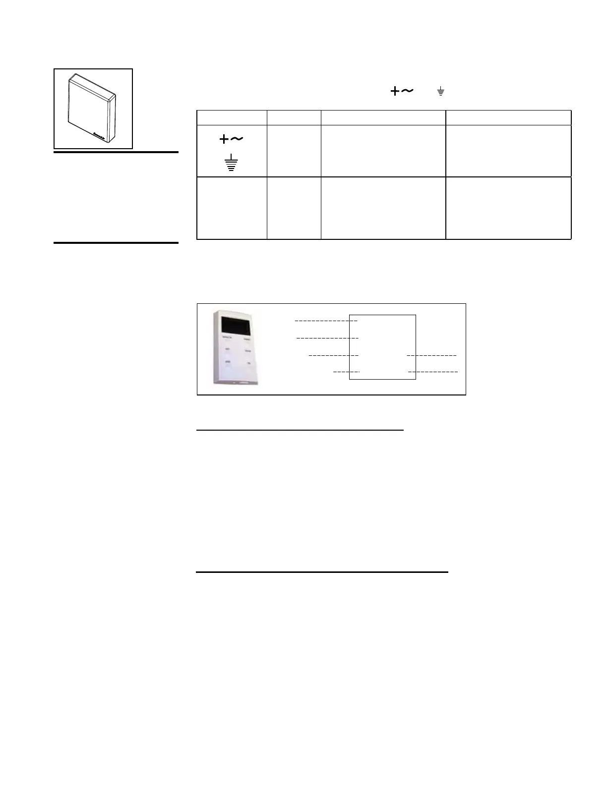
Option VFC7, Wall Stat for Low/Medium/High Fan Control
A eld-installed thermostat, P/N 222756, is used for blower override. Follow the manu-
facturer's instructions for mounting the wall stat. See wiring information below and on
the unit wiring diagram. Thermostat is 24V.
RNET +
RNET -
+12V
GND
OPTIONAL WALL STAT
FIGURE 29D - Wall Stat,
P/N 222756, used with
Option VFC7
Neutral Air Control System (Option D15)
In the Occupied Mode, startup is determined by the outside air temperature (OAT). If
the outside air temperature is above 68°F, the system starts in the cooling mode. If the
outside air temperature is below 68°F, a MAPS
®
unit with a heat section starts in the
heating mode. The heating/cooling mode is then set by the controlling temperature
requirements. A unit with cooling and heating operates to maintain the user selected
discharge air temperature setpoint for either cooling or heating mode. Upon proof of
fan status, mechanical heating and cooling systems operate to maintain the setpoint
if the ambient conditions permit the function. There is a 120 second delay (Mode
Changeover Timer) between a change of heating and cooling equipment and mode.
In the Unoccupied Mode, the unit is off.
8.3 Control Options
(See Form CP-MAPS
D15/16 for additional
information on Option
D15 and Option D16.)
Space Temperature Control System (Option D16)
In the Occupied Mode, startup is determined by the outside air temperature (OAT). If
the outside air temperature is above 68°F the system starts in the cooling mode. If the
outside air temperature is below 68°F, a MAPS
®
unit with a heat section starts in the
heating mode.
The heating/cooling mode is then set by the controlling temperature requirements.
If the space temperature is 2°F above the space cooling setpoint, and the OAT is
above the mechanical cooling lockout, the unit will switch to space cooling mode. If the
space temperature is 2°F below the space heating setpoint and the OAT is below the
mechanical heating lockout, a system with a heat section will switch to space heating
mode. There is a 120 second delay (Mode Changeover Timer) between a change of
heating and cooling equipment and mode.
On proof of fan status, the unit maintains the space temperature setpoint according to
the mode sequence. In the Unoccupied Mode, the unit will run intermittently to maintain
night setup/setback temperatures.

 Loading...
