Form I-MAPSIII&IV, Page 44
7.6 Condenser Fan Motors and Fans
All condenser fan motors are direct-drive, statically and dynamically balanced, and
permanently lubricated. Condenser fan motors are open dripproof motors with exter-
nal sling protection against water penetration and have auto reset thermal overload
protection.
Area above the fans should always be unrestricted and open.
7.7 Compressors
All of the compressors are high efciency hermetic scroll type designed for use with
R-410A refrigerant. Circuit A, B, C, and D cooling compressors are in the Compressor
Section. Circuit E or Dh compressor (reheat) is located in the cabinet lter section.
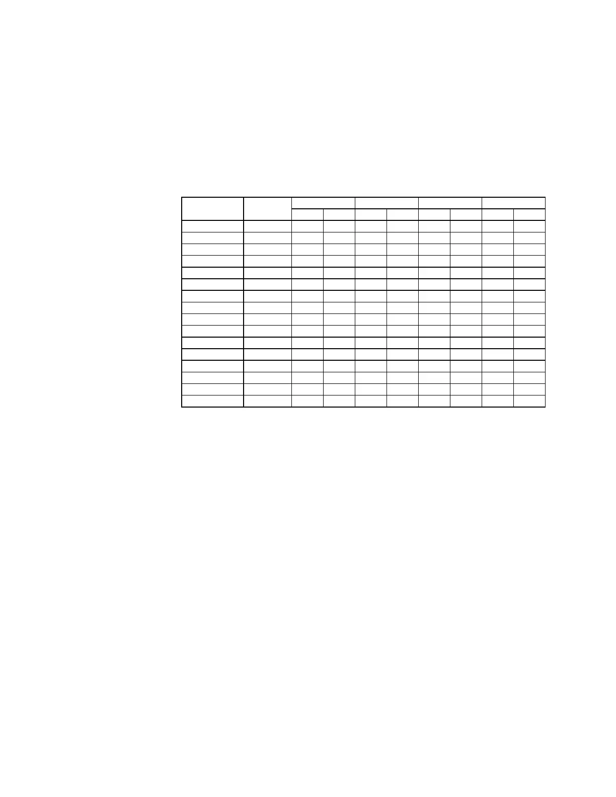
Compressor
Model
ARI
Tonnage
208 V 230 V 460 V 575 V
RLA LRA RLA LRA RLA LRA RLA LRA
ZP24K5E 2 9.6 58.0 9.6 58.0 5.1 28.0 3.3 23.7
ZP36K5E 3 13.5 88.0 13.5 88.0 6.0 44.0 4.9 34.0
ZP54K5E 4.5 15.6 110 15.6 110 7.8 52 5.8 38.9
ZP57K3E 5 20.5 155 20.5 155 9.6 75 7.6 54
ZP61KCE 5 19.0 123 19.0 123 9.7 62 7.4 50
ZPD61KCE 5 20.4 156 20.4 156 9.7 62 7.4 50
ZP72KCE 6 23.2 164 23.2 164 11.2 75 7.9 54
ZP83KCE 7 25.0 164 25.0 164 12.2 100 9.0 78
ZPD83KCE 7 24.0 187 24.0 187 12.6 100 9.9 78
ZP120KCE 10 33.3 239 33.3 239 17.9 125 12.8 80
ZP137KCE 11 48.1 245 48.1 245 18.6 125 14.7 100
ZPD137KCE 11.4 48.1 245 48.1 245 18.6 125 14.7 100
ZPT144KCE 12T 23.2 164 23.2 164 11.2 75 7.9 54
ZP154KCE 12 51.3 300 51.3 300 23.1 150 19.9 109
ZPDT14MCE 12 46.4 164 46.4 164 22.4 75 15.8 54
ZP182KCE 15 55.8 340 55.8 340 26.9 173 23.7 132
Compressor Amps/
Voltage
7.0 Electrical and
Wiring (cont'd)
(For additional information,
refer to the Operation/
Maintenance/Service
Manual, either Form
O-MAPS Cabinets A/B/C or
Form O-MAPS Cabinet D)
Mechanical Compressor Protection - A low pressure cutoff (LPCO) switch is used for
protection against compressor damage due to a loss of system charge. This protection
prevents short cycling on the internal overload (IOL) which can pump the oil out of the
compressor.
All compressors also have manual reset high pressure cutouts (HPCO) and frost
stats.
Compressor Staging (RCB, RDB, RDCB, RDDB, RECB. REDB) - Each system
leaves the factory with the compressor staging sequence set. The compressor will
start based upon a call for cooling to maintain the discharge air temperature setpoint.
There is a minimum 240 second ON and OFF time for each stage (not compressor).
Compressor Modulation (RCC, RDC, RDCC, RDDC, RECC. REDC) - These units
have scroll compressors equipped with modulating valves and a digital controller that
interfaces the compressor with the system controller. Compressor operation will start
based upon a call for cooling and will modulate to maintain the discharge air tempera-
ture setpoint. There is a ve-minute compressor on/off time.
For additional information about compressor operation, see the Operation/Mainte-
nance/Service Manual.
Crankcase Heaters - Each compressor has a band-type crankcase heater. Crankcase
heaters must always be energized for at last 24 hours prior to operating the compres-
sor.
If ordered with Option AUC9, the bypass valve will provide expanded compressor
modulation at low outside air temperatures by allowing some of the gas from the suc-
tion line to be re-routed directly to the evaporator coil. With Option AUC9, at least one
circuit per stage has a hot gas bypass valve.
Hot gas bypass valves are factory set. However, the factory setting should be checked
at startup. To check the valve operation and/or make eld adjustments, it is necessary
to simulate a light load condition as described below.
Optional Hot Gas
Bypass
Condenser Fan Control
1. The unit has a maximum of four condenser fans.
2. The condenser fans are electrically tied to the compressors.
3. The condenser fans on "D" Cabinet systems are grouped into two banks.

 Loading...
