Form I-MAPSIII&IV, Page 52
8.0 Controls
(cont'd)
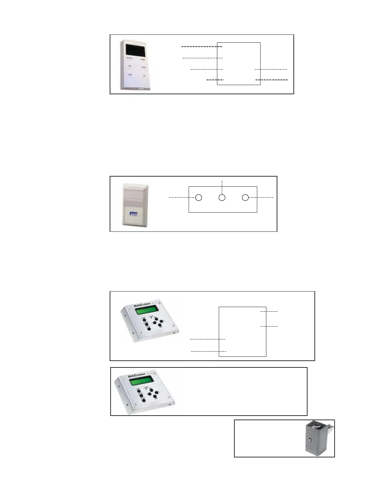
FIGURE 30 - Wall
Mounted Temperature
Sensor, P/N 222756, is
Std in D16; Option CL77
if ordered with Control
Option D15
RNET +
RNET -
+12V
GND
OPTIONAL WALL STAT
Wall-Mounted Space
Humidity Sensor
The room humidity sensor allows for space control of humidity with dehumidication
Models RDB, RDDB, REDB, RDC, RDDC, REDC. See below and the unit wiring dia-
gram for electrical connections.
8.3 Control Options (cont'd)
Wall-mounted Setpoint Interface (Override) - The wall temperature sensor is stan-
dard with D16 and allows the occupant to change the space temperature setpoints
for cooling and heating. In addition, the user has optional high-medium-low fan speed
control or heat-cool-auto-off control. Other functionality includes occupied override
timer and display of unit alarm codes and key temperature values. It also displays the
outside air temperature and humidity, discharge air temperature, and fan status. See
below and unit wiring diagram for electrical connections.
OPTIONAL ROOM
HUMIDITY SENSOR -DT7
V OUT
GND
V+
FIGURE 31 -
Room Humidity
Sensor, Option DT7,
P/N 234822, and Field
Wiring Connections
Optional Control
Modules
Both the wall-mounted control module, Option RB3, and the hand-held module, Option
RB4, include alarm lights and access to menus. See Form CP-MAPS D15/D16 for
information.
The wall-mounted control module requires eld installation. Follow the manufacturer's
recommendations when selecting a location and mounting the control. Refer to the
control manual, Form CP-MAPS 15/16, for installation instructions and to the wiring
diagram for eld wiring connections.
FIGURE 32A - Wall-
Mounted Control
Module, Option RB3,
P/N 222189, and Field
Wiring
GND
+12V
RNET -
RNET +
BACview5 LCD
(MOUNTED IN SPACE)
OPTIONAL REMOTE DISPLAY
SUPPLIED
12 V
FIELD
FIGURE 32B -
Hand-Held Control
Module, Option RB4,
P/N 258452
Hand-held control has a 12-ft
cable that will plug into either
the wall mounted Option CL77
temperature sensor or the unit-
mounted controller.
FIGURE 33 -
Option BD5,
Firestat (200°F),
P/N 42782
Firestat is for eld installation in either the
return air or outlet air ductwork. Follow
instructions supplied with the control.
Follow wiring diagram on the unit. Comply
with local building codes.
Optional Firestat

 Loading...
