Form I-MAPSIII&IV, P/N 222917R9, Page 5
FIGURE 1A - Sample of System
Rating Plate (applies to all models)
System Rating Plate Key:
A = Model
B = Manufacturing Date (Month/Year)
C = Blower Motor HP
D = Volts/Phase/Hertz
E = Full Load Amps of Blower Motor
F = Minimum Circuit Ampacity
G = Maximum Fuse Size
H = Quantity - Compressor A
I = Rated Load Amps of Compressor A
J = Locked Rotor Amps of Compressor A
K = Quantity - Compressor B
L = Rated Load Amps of Compressor B
M = Locked Rotor Amps of Compressor B
N = Quantity - Compressor C
O = Rated Load Amps of Compressor C
P = Locked Rotor Amps of Compressor C
Q = Quantity - Compressor D
R = Rated Load Amps of Compressor D
S = Locked Rotor Amps of Compressor D
GG = Quantity - Compressor E
HH = Rated Load Amps of Compressor E
II = Locked Rotor Amps of Compressor E
T = Quantity Condenser Fan Motors
U = Rated Load Amps of Condenser(s)
V = Refrigerant Charge (lbs) - Circuit A
W = Refrigerant Charge (lbs) - Circuit B
X = Refrigerant Charge (lbs) - Circuit C
Y = Refrigerant Charge (lbs) - Circuit D
JJ = Refrigerant Charge (lbs) - Circuit E
Z = Condenser Fan Motor HP
AA = Test Pressure High (psig)
BB = Test Pressure Low (psig)
CC = SCFM Airow
DD = External Static
Pressure (" w.c.)
EE = Drive (Option AM)
FF = Wiring Diagram No.
Gas Heat Section Rating Plate Key:
AA/A = ANSI Standard Date
AA1/A1 = CSA Standard Date
C = Model No.
D = Voltages
E = Type of Gas (natural)
F = Orice Size
H = Normal BTUH Input (sea level)
I = Thermal Output BTUH (sea level)
J = Minimum BTUH Input (sea level)
K = Manifold Pressure
L = Minimum Gas Supply Pressure
M = Maximum Throughput
N = Minimum Throughput
P = Manufacturing Date (Month/Year)
Q = Altitude in Feet
R = Altitude in Meters
FIGURE 1B - Sample of a Gas
Heat Section Rating Plate
REZNOR
®
MERCER, PA., U.S.A. 16137
MADE IN USA
FOR INDUSTRIAL/COMMERCIAL USE ONLY
SUITABLE FOR OUTDOOR USE
MODEL [ A ] [ B ]
SERIAL NO. [ ]
ELECTRICAL
[D] VOLTS +/- 10% [D] PHASE [D] HZ
MINIMUM CIRCUIT AMPACITY (MCA) [ F ] AMPS
MAXIMUM FUSE SIZE/*CKT BREAKER [ G ] AMPS
QTY FLA(EA) HP(EA)
SUPPLY AIR BLOWER MOTOR 1 [ E ] [ C ]
CONDENSER FAN MOTOR (S) [ T ] [ U ] [ Z ]
QTY RLA (EA) LRA (EA)
COMPRESSOR A [ H ] [ I ] [ J ]
COMPRESSOR B [ K ] [ L ] [ M ]
COMPRESSOR C [ N ] [ O ] [ P ]
COMPRESSOR D [ Q ] [ R ] [ S ]
COMPRESSOR E [ GG ] [ HH ] [ II ]
CIRCUITS A B C D E
REFRIGERANT - R-410a CHARGE - LBS
[ V ] [ W ] [ X ] [ Y ] [ JJ ]
TEST PRESSURES HIGH 600 PSIG LOW 45 PSIG
EQUIPPED FOR OPERATION AT AN AIR FLOW OF [ CC ] SCFM
AGAINST A STATIC PRESSURE OF [ DD ] INCHES WATER COLUMN
DRIVE RPM [ EE ]
WIRE DIAGRAM [ FF ]
REFER TO RATING PLATE IN THE FURNACE SECTION (WHEN USED)
FOR ADDITIONAL INFORMATION.
*HACR TYPE REQUIRED PER NEC
REZNOR
®
MERCER, PA USA 16137
DUCT FURNACE/GÉNÉRATEUR D'AIR CHAUD À GAINE
CATEGORY III/CATÉGORIE III
FOR INDUSTRIAL/COMMERCIAL USE ONLY
POUR USAGE INDUSTRIEL/COMMERCIAL
ANSI Z83.8 [AA] - [ A ]
CSA 2.6 [AA1] - [A1] DUCT FURNACE/GÉNÉRATEUR D'AIR CHAUD À GAINE
MODEL/MODÈLE [ C ] [ P ]
SERIAL NO. / #DE SÉRIE: [ ]
VOLTAGE [ D ]
TYPE OF GAS/TYPE DE GAZ: [ E ]
ALTITUDE [ Q ] FEET/PIEDS, [ R ] MÈTRES
BURNER ORIFICE SIZE [ F ] DRILL HAS BEEN FACTORY ADJUSTED
BRULEUR DIMENSION DE L'ORIFICE [ F ] FORET
NORMAL INPUT/ENTRÉE NORMALE (TOTAL)
[ H ] BTU/HR
THERMAL OUTPUT / RENDEMENT THERMIQUE (TOTAL)
[ I ] BTU/HR
MINIMUM INPUT/ENTRÉE MIN.
[ J ] BTU/HR
NORMAL MANIFOLD PRESSURE
[ K ] IN.W.C.
PRESSION NORMALE DE LA TUB
[ K ] PO/COL D'EAU
MIN. PERMISSIBLE GAS SUPPLY PRESSURE
FOR PURPOSE OF INPUT ADJUSTMENT.
[ L ] IN.W.C.
PRES. D'ALIM. MIN. ACCEPTABLE DE GAZ POUR
DES FIN DE RÉGLAGE DE L'ENTRÉE
[ L ] PO/COL D'EAU
MAXIMUM THROUGHPUT / MINIMUM THROUGHPUT [ M ] / [ N ] C.F.M.
CONSOMMATION MAXIMUM / MINIMUM [ M ] / [ N ] PI3/MN
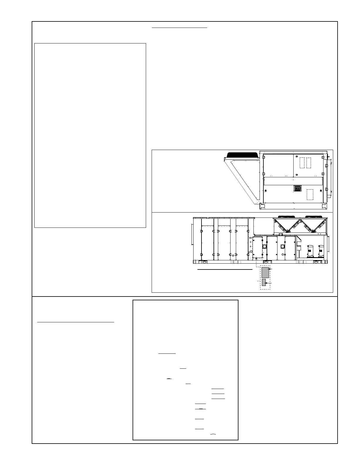
System Rating
Plate(s)
Rating Plate for
Gas-Fired Furnace on
Models RDCC & RDDC
MAPS® Cabinets A, B, and C -
System Rating Plate(s) are on
the inside of the High Voltage
Electrical Compartment Door
Filter
Access
Coil
Access
Fan & Motor
Access
Control
Access
Heat
Access
Heat
Access
Left Side View (Control Side)
MAPS® Cabinet D
Wiring Diagram
Rating Plate
(inside of control access door)
Rating Plate
Location - Cabinets
A, B, and C
Rating
Plate
Location -
Cabinet D

 Loading...
