Form CP-MAPSIII-D21, Doc No 303070, Page 3
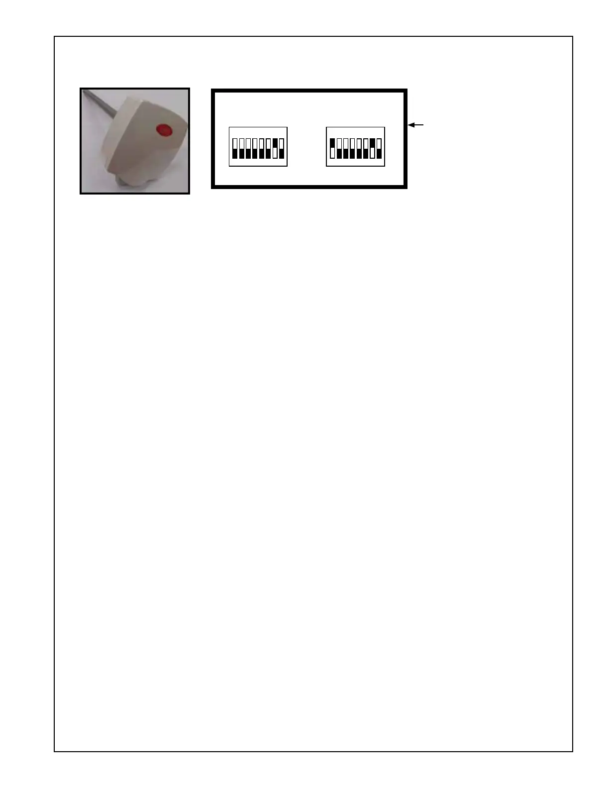
1 2
3 4 5 6 7 8
ON
1 2
3 4 5 6 7 8
ON
RETURN AIR DIP SWITCH
POSITIONS 1 & 7 “ON”
EXHAUST DIP SWITCH
POSITION 7 “ON”
ADDRESS 128
RETURN AIR TEMP & HUMIDITY
SENSOR
ADDRESS 129
EXHAUST AIR TEMP & HUMIDITY
SENSOR
Exhaust Air / Return Air
Temp & Humidity Sensor
Addressable Dip Switch
Settings: Factory set when
ordered on new production
units.Forretrotstheuser
must set the addresses
accordinglyintheeld.
Optional Exhaust Air / Return Air Temp & Humidity Sensors:
These sensors are duct mount style and operate on a RS-485 communication trunk.
Note: Refer to the Installation
manual and or unit wiring
drawingsforspecicwiring
information.