Form CP-MAPSIII-D21, Doc No 303070, Page 4
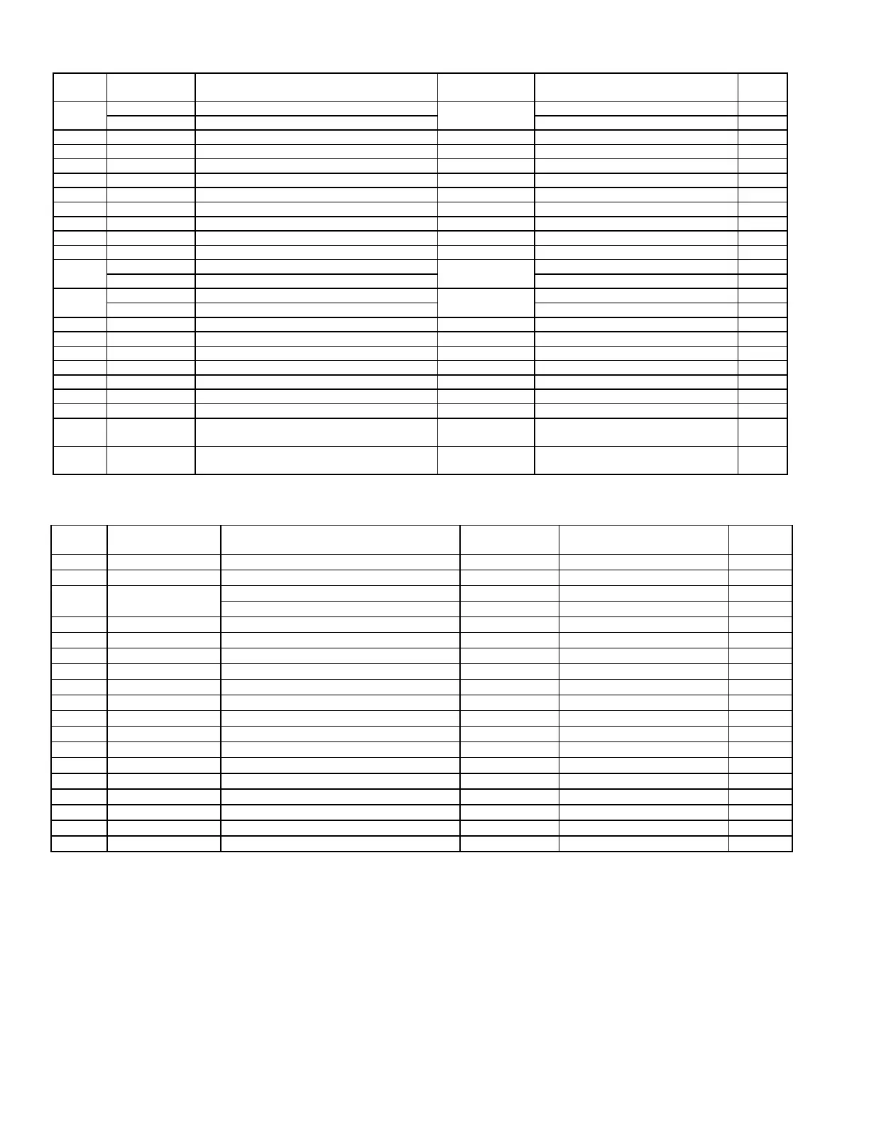
1.3 Controller hardware input – output points
Input
Terminal
Input Point
Name
Input Description Signal type Signal Range
Always
Active
J23
FB2
Spc_Temp Space Temp - up to a total of 6 inputs
RS-485
Communication
Spc_Humidity Space Humidity - up to a total of 6 inputs
U1 OA_Hum_Raw Outside Air Humidity 0 -10 Vdc 0 to 100% RH x
U2 OA_Temp_Raw Outside Air Temp Thermistor 10K-2 -35 °F to 240 °F (-37°C to 115°C) x
U3 Ext_Dmpr_Cmd External Unit Damper Command 0 -10 Vdc 0 to 100%
U4 DA_Temp Discharge Air Temp Thermistor 10K-2 -35 °F to 240 °F (-37°C to 115°C) x
U5 CC_Temp Cooling Coil Discharge Air Temp Thermistor 10K-2 -35 °F to 240 °F (-37°C to 115°C) x
U6 MA_Temp Mixed Air Temp Thermistor 10K-2 -35 °F to 240 °F (-37°C to 115°C) x
U7 Bldg_Pressure Building Static Pressure 0 - 10 Vdc -0.5” iwc thru + 0.5”iwc
U8 Duct_Pressure Duct Static Pressure 0 - 10 Vdc 0 - 2.5” iwc
U9 Spc_CO2 Space CO
2
0 - 10 Vdc 0 - 2,000 ppm
J26
FB2
RA_Temp Return Air Temp
RS-485
Communication
RA_Humidity Return Air Humidity
J26
FB2
EA_Temp Exhaust Air Temp
RS-485
Communication
EA_Humidity Exhaust Air Humidity
ID1 SF_Sts Supply Fan Status Dry Contact Open = “OFF” / Close = “ON” x
ID2 Filter_Sts Main or ERV Dirty Filter Status Dry Contact Open = “OFF” / Close = “ON”
ID3 Safety_Sts Safety Input Status Dry Contact Open = “ALARM” / Close = “NORMAL” x
ID4 Ext_OCC Occupied Mode Input Dry Contact Open = “OFF” / Close = “ON”
ID9 Ext_ Switch_1 External Damper Position Sw 1 Dry Contact Open = “OFF” / Close = “ON”
ID10 Ext_ Switch_2 External Damper Position Sw 2 Dry Contact Open = “OFF” / Close = “ON”
ID14 Phase_Alarm Phase Protection Alarm Dry Contact Open = “OFF” / Close = “ON”
ID15 Htr_1_Sts Gas Heater 1 Status
Rib Relay N.O.
Contact
Open = “OFF” / Close = “ON”
ID16 Htr_2_Sts Gas Heater 2 Status
Rib Relay N.O.
Contact
Open = “OFF” / Close = “ON”
Output
Terminal
Output Point Name Output Description Signal / Range Signal Range
Always
Enabled
Y1 Damper_Cmd Damper Output Command 0 – 10Vdc 0 – 100% Open x
Y2 SF_VFD_Cmd Supply Fan VFD Command 0 – 10Vdc 0 – 100% Flow
Y3 HX1_Mod_Cmd
Gas Heating 1 Modulation Command 2 – 10Vdc 0 – 100% Capacity
Electric Heating Modulation Command 0 – 10Vdc 0 – 100% Capacity
Y4 HX2_Mod_Cmd Gas Heating 2 Modulation Command 2 – 10Vdc 0 – 100% Capacity
Y5 RH_Mod_Cmd Reheat Modulation Command 0 – 10Vdc 0 – 100% Capacity
NO1 SF_Cmd Supply Fan Command 24Vac Contact Open = “OFF” / Close = “ON” x
NO2 Comp_Stg1_Cmd Compressor Stage 1 Command 24Vac Contact Open = “OFF” / Close = “ON” x
NO3 Comp_Stg2_Cmd Compressor Stage 2 Command 24Vac Contact Open = “OFF” / Close = “ON”
NO4 Comp_Stg3_Cmd Compressor Stage 3 Command 24Vac Contact Open = “OFF” / Close = “ON”
NO5 Comp_Stg4_Cmd Compressor Stage 4 Command 24Vac Contact Open = “OFF” / Close = “ON”
NO7 Alm_Rly_Cmd Unit General Alarm Relay Command 24Vac Contact Open = “OFF” / Close = “ON” x
NO8 HX_Stg1_Cmd Heating Stage 1 Command 24Vac Contact Open = “OFF” / Close = “ON”
NO9 HX_Stg2_Cmd Heating Stage 2 Command 24Vac Contact Open = “OFF” / Close = “ON”
NO10 HX_Stg3_Cmd Heating Stage 3 Command 24Vac Contact Open = “OFF” / Close = “ON”
NO11 HX_Stg4_Cmd Heating Stage 4 Command 24Vac Contact Open = “OFF” / Close = “ON”
NO12 HX_Stg5_Cmd Heating Stage 5 Command 24Vac Contact Open = “OFF” / Close = “ON
NO13 HX_Stg6_Cmd Heating Stage 6 Command 24Vac Contact Open = “OFF” / Close = “ON”
NO17 RH_Cmd Reheat compressor Command 24Vac Contact Open = “OFF” / Close = “ON”