5. Secure concentric adapter box to underside of roof (see Figure 12):
a. Insert combustion air pipe through roof as shown in Figure 13, DETAIL A.
b. Position concentric adapter box to match pipe runs and secure box to underside of roof using field-supplied
hardware.
6. Install terminal-end vent pipe:
NOTE: The length of the terminal-end vent pipe is determined by the installation within maximum
and minimum requirements. The vent pipe extending through the box, through the combustion air
inlet pipe, and above the combustion air inlet air pipe must be one piece without joints.
a. Refer to Figure 13 to determine required length of continuous section of vent pipe. Determine length as follows:
1) start with at least 6 inches (152 mm) below concentric adapter box for connecting to coupler, 2) plus 6 inches
(152 mm) through box, 3) plus length of combustion air pipe, 4) plus minimum of 23 inches (584 mm) beyond
top of combustion air pipe—total is minimum length of vent pipe section.
NOTE: A longer vent pipe may be required.
b. Ensure that vent pipe is in proper flow direction and slide end of pipe into box and out through combustion air
pipe. Position vent pipe to lengths determined above.
c. Ensure that silicone ring is seated properly and connect terminal vent pipe to vent pipe run.
d. Recheck silicone ring to ensure that it is still properly seated.
7. Install indoor combustion air pipe:
a. Secure single-wall combustion air pipe run to collar on concentric adapter box using field-supplied sheet metal
screws.
b. Seal pipe joint using tape or sealant.
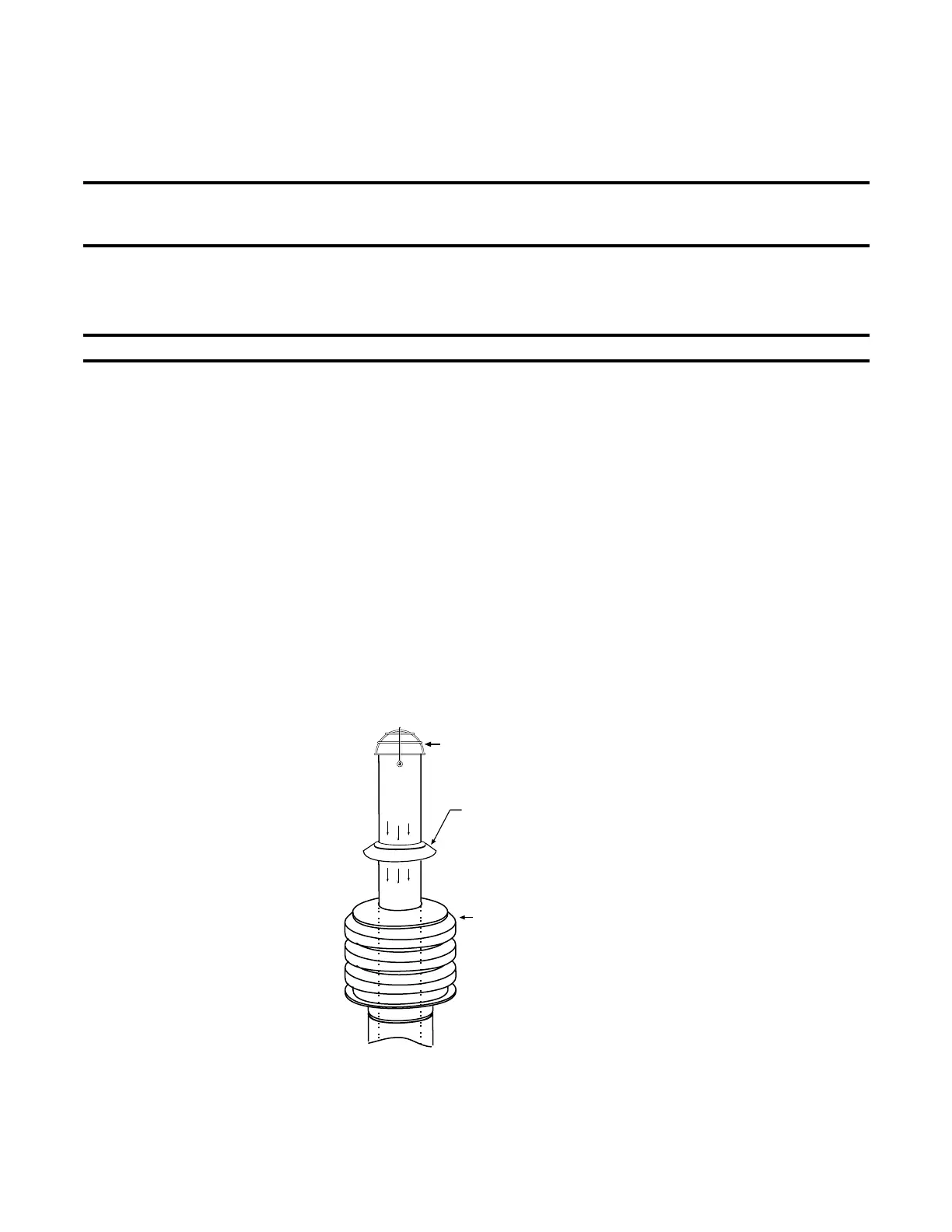
8. Install outdoor combustion air inlet, rain collar, bird screen, and field-supplied flashing (see Figure 14):
a. Slide combustion air inlet over vent pipe and secure collar to combustion air pipe using sheet metal screws.
b. Seal pipe joint using tape or sealant.
c. To prevent rainwater leakage, slide rain collar over end of 4-inch vent pipe and seat it flush on top of combustion
air inlet. Do not paint or use petroleum based products on rain collar (silicone sealant is allowed).
d. Install bird guard and secure using two sheet metal screws provided.
e. Flash combustion air pipe on outside using field-supplied flashing.
Figure 14. Combustion Air Inlet, Rain Collar, and Bird Guard
9. Verify compliance with Figure 12 and with all specifications listed in Venting and Combustion Air
Requirements and Hazards of Chlorine sections.
RAIN COLLAR
COMBUSTION AIR INLET
BIRD GUARD
23
I-UEZ (04-21) 1034347-0

 Loading...


