RF Explorer User Manual page 18
Understanding RF Power Modes
The RF Explorer Signal Generator delivers 8 different power levels, nominally specified as per table below:
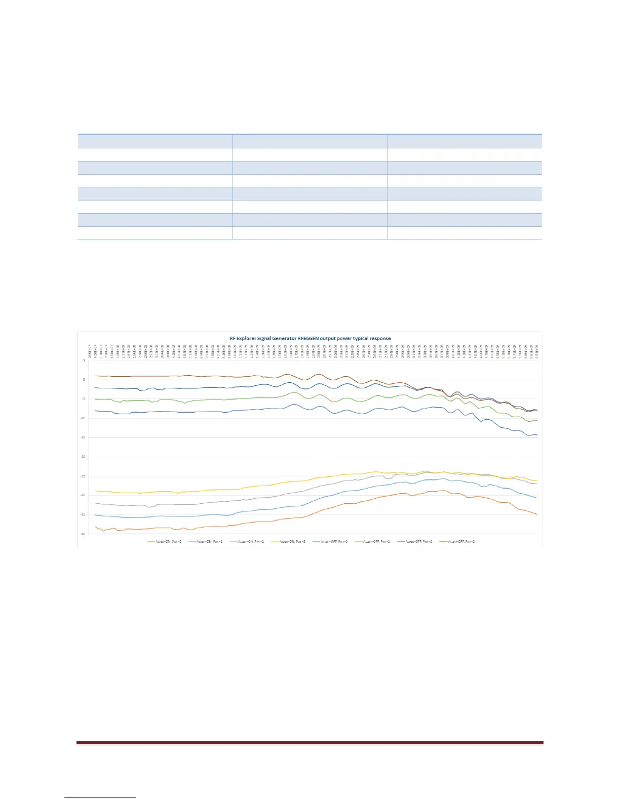
These are ideal power levels that are not actually constant with frequency. Actual power levels are a
function of frequency, as depicted in graph below. This graph is generic but every RF Explorer Signal
Generator includes an internal calibration table, produced in the factory at calibration time, with actual
values for accurate reading on screen.
The delivered power levels have a linear response up to about 2GHz, for higher frequencies there are some
roll off and power becomes predictable but not constant. The unit is fully calibrated and includes an internal
amplitude calibration table to allow accurate power normalization and measurement done in Tracking
mode.
The exact power level available on each frequency point is available on screen, as well as in the RF Explorer
for Windows application. If you need more details or power level accuracy is important to you, please
contact us.
A future Hardware module upgrade, available for connection on the internal expansion port, will allow for
additional power modes with finer granularity, higher power values and flat frequency response as an
option.